Configuring Automatic Controls
This section will help you learn how to configure devices for automatic controls. The system has the capability to automate the operation of any externally connected equipments ( the equipments connected to relay of this device). All needed automation can be done by configuring the device without the need for any programming. It is also possible to configure devices such that one device senses values of the sensors connected to it and another device sitting remotely takes an action based on those sensed values.
1 Configuring an Output Port for auto OFF mode
Normally when a port of a device is activated, that port stays in that until changed.
For example, if you put a port ON, the state of that port stays ON until you press that button again to put it OFF.
If you want, you can configure the device such that it automatically puts its port OFF after a specified duration of time. Suppose that you want the port to be automatically put off 6 seconds after it is manually put ON. If so, configure as follows:
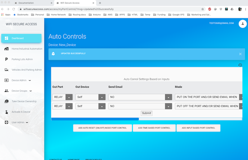
Click on 'Configure Auto Controls' under Device Admin in the Dashboard menu. If you have more than one device, it may either prompt you to choose a device, or may use the previous used device depending on the current state of your configuration. Once the device is selected, it will take you to the Port Controls page which will look similar to Fig 42, if you have not yet configured any auto controls yet. If you had earlier configured any auto controls for this device, it will list all the previously configured auto controls here
Note: If the device is in access control, you will see three rows of controls which are pre-popilated. You cannot deleted any of them, but some of its parameters can be chnaged. Shown below is a of a device that is not in access control mode. Auto-reset has been pre-added in a device in access mode, and you cannot add another one. Also, if your access control device is hardware type less than 4, you will not be able to add any more auro controls.
![]()
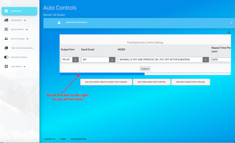
Now, press the button labelled 'ADD AUTO RESET (ON/OFF) MODE PORT CONTROL'. That will take you to a page similar to Fig 43.
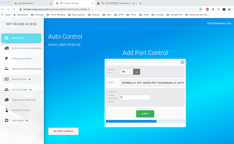
On this page, select the output port from the pull-down options. The available options are all the output ports of this device. In the second row, it shows the mode. There is no option here. The mode is pre set to "NORMALLY OFF, WHEN PUT ON MANUALLY, AUTO PUT OFF AFTER DURATION".
Then enter the duration of time in seconds after which the port should be auto reset. If you enter 0, it will never reset that port and will stay ON until you manually put it OFF. Then press Submit. If you have entered everything correctly, it will configure the device accordingly and will display the port control page of the device (similar to Fig 44) displaying all your configured port controls of this device.
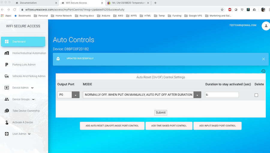
If you need, you can edit this port control on this page. If you want to delete this portcontrol, scroll the page to the right to see the Delete checkbox at the right end of this portcontrol. If you check that box and press Submit, it will delete this portcontrol.
The port is now configured such that the port automatically gets reset after the specified duration whenever you activate this port. Try to activate this port using a smart phone or computer and test if its is working.
2 Configuring Periodic Actions (Interval Based)
You can configure a periodic action on any of the output ports. For example, say, you want to put ON an equipment connected to a device at the start of every hour. If so, configure it as follows:
Click on 'Configure Auto Controls' under Device Admin in the Dashboard menu. If you have more than one device, it may prompt you to choose the device, or may use the device that you used last depending on the environment. Once the device is selected, it will display a page similar to Fig 42 showing all the current auto controls configured on this device. If you want to configure Relay to come ON at every hour, click on 'ADD TIME BASED PORT CONTROL' on this page. That will display a page similar to Fig 45.
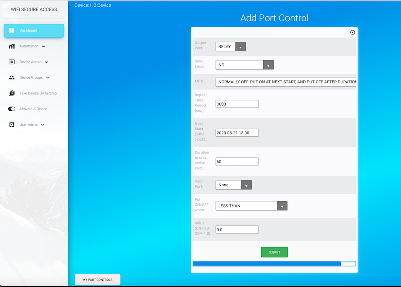
On this form, select the Out Device. This is the device that you want to activate on a timely basis. This can be 'Self' for this device, or any other device that you own. You can select it from the pulldown menu. If this control is not dependant on any of its input port, it will not let you choose an out device other than this device. Then select the 'Out Port'. The pulldown menu shows the outport ports. If you have not changed the out device, this pull down menu is for the out device. ZBut, if you changed the Out Device, it will prompt to again to select this from a new menu when you press Submit button. If you are configuring Relay(or, whatever the name that you have assigned to this port) of this device, select tht for Output Port on this page.
Next, select the action to be executed on the selected port of the selected device. The actions can be either one of 'ON', 'OFF', 'Disable Device', 'Enable Device' or 'Notification only'.
Next, select notification type from the pulldown menu. Notifications can be either email or calling a webhook (a url as set in the "configure Device' of this device, or a combination of these two. The the email address used for sending notifications is the one set for 'Alert Email' field in the 'Configure Device' menu.
Then, set the 'Repeast Time period' for this repteaded action. This must be in seconds. For example, if you want the relay to be activated every hour, enter 3600 in this field (1 hour = 3600 seconds).
Then select the 'Initial Start'. Initial Start field can be either a time delay in seconds from now, or an exact date and time in the future. If you leave this as blank, it will be taken "start immediately". If you are entering the exact date and time when this should start, then enter in 24 hour clock. Its format is yyyy-mm-dd hh:mm. You need to specify the year, month, date, hour and minutes in this format.
In the next field, enter the duration in seconds the relay should remain ON. If you want the out-port to be on for 1 minute, enter 60 here. Keep in mind that this duration must be less than the repeat time interval for obvious reasons.
Note: This is a periodic interval based control. That means that the repeat action is performed after the specified interval. If you configure interval based periodic control for scheduling actions every day, or every Tuesday of every week, this may not work well if the daylight saving time changes. You will have to modify this control when daylight saving changes.
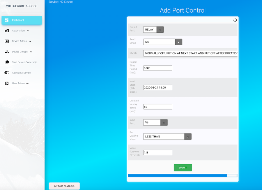
There are three more additional fields in this form. They are optional fields. You can leave them as they are if you are only interested in just a periodic action. However, if you want the periodic action to take place only when a condition is met, then you can enter that information here. For example, say, you want RELAY to come ON periodically every hour only if a sensor detects a pre-set value. If so, connect that sensor to the inputs of this smart device. The sensors can be motion sensor, temperature sensor, rain sensor and so on.
These sensors can be cabled to the green screw terminals of the controller PCB inside the box. Or, you can use a sensor that is available from Bhadre. If you have cabled any sensor to the controller, that must be set in 'Configure Device' menu prior to using that sensor for controls. Once set, these dsensors will be seen in the pulldown menu of 'Input Port'.
Select input port to which sensor is connected. Then in the next field, choose the logical operation (LESS THAN. or GREATER THAN OR EQUAL TO). Then enter the pre-set value of the sensor in the Value field. Fig 45A shows an example of such entry. By selecting these three fields appropriately, you are configuring the smart device to put on the OutPort periodically only if the value sensed at the Inport is either less than (or greater than or equal to) the Value. As mentioned earlier, if you leave input port as None, it will ignore this condition when activating periodic actions.
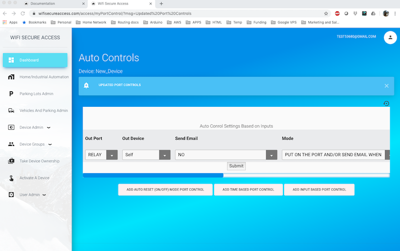
Once all these fields are entered press Submit. If all entered values are valid, it will configure the device accordingly and display the portcontrol page similar to Fig 46. If there is any error, it will display errors. If errors are reported, fix those errors and enter the values again and re-submit. Fig 46 will show all the port controls configured in this device (the currently configured as well as all previously configured and still active). You can delete any of these port controls any time by checking delete button (at the far right of each row) and by pressing Submit button.
Note: If you do not want the action to be repeated, but just only once at the Next-Start, set Repeat Time interval as 0 when creating portcontrol
You can delete this portcontrol or any portcontrols that you have configured by checking the delete box against that portcontrol in the portcontrols page (Fig 46) and pressing Submit button. Note that the delete checkbox is all the way at the right of the form. You may have to scroll the bottom bar of that form to find it.
Note: You can configure periodic port controls on any of your device to send you emails even without activating an output port. For example, say, you want emails sent to the 'Alert Email' address every hour starting at 8:00AM, 2021-02-15 as a reminder. You can do that exactly the same way as you have configured above, except that when selecting fields, select None for Output port and choose the 'Notification Type'. Note: Alert email is the email address set in the Alert Email' field in the 'Configure Device' screen. Unless set, it defaults to the email address of the owner of the device. webhook is not set by default. You need to set that in "Configure Device' menu. webhook is a url of you application. That url will be called with a day in JSON format whenever timer action is executed.
The fields 'Notification Webhook URL' in the 'Configure Device' menu is the URL of your webhook to which a call will be made when conditions are met to send notifications. Webhook key/token is the key or the token of your webhook. You may enter those in these two fields, if you are interested in making such calls to send notifications. If the Webhook URL is left blank, it will not make any such calls to webhook URL. The call is an HTTPS POST call with the key token in the header ('Authorization': webhook_key), and with some data in the body in JSON format. The data will have the device name, sensor_name, current value of the sensor, and a message. The following is the type of call that will be made:
HTTPS POST call
url: The Notification webhook URL configured
headers = {'Authorization': webhook_key, 'Content-Type': 'application/json', 'Accept': 'application/json',}
data = {"controlDevice": control_device, "sensorDevice": sensor_device, "sensor": sensor_name, "message": msg_webhook, "currentVal": current_value, "limitSet": limitVal, "msg_code": msg_code}
requests.post(notification_webhook, data=json.dumps(data), headers=headers)
Your application program can use this information and take any needed action. This is an optional feature that you can implement, if you want.
3 Configuring port control based on Input Condition
You can configure an output port to be put ON/OFF based on an input sensor values. Fo example, you can configure an output port to be put ON when the voltage level at Vin is greater than or equal to 1.0volts. Or you can configure it to be automatically put ON when the temperature read by DS18B20 Temperature Sensor connected to D7 is 60 degree or higher. Or, you can configure Buzzer to be activated when the motion sensor connected to D6 senses a motion, and so on for any of your requirements.
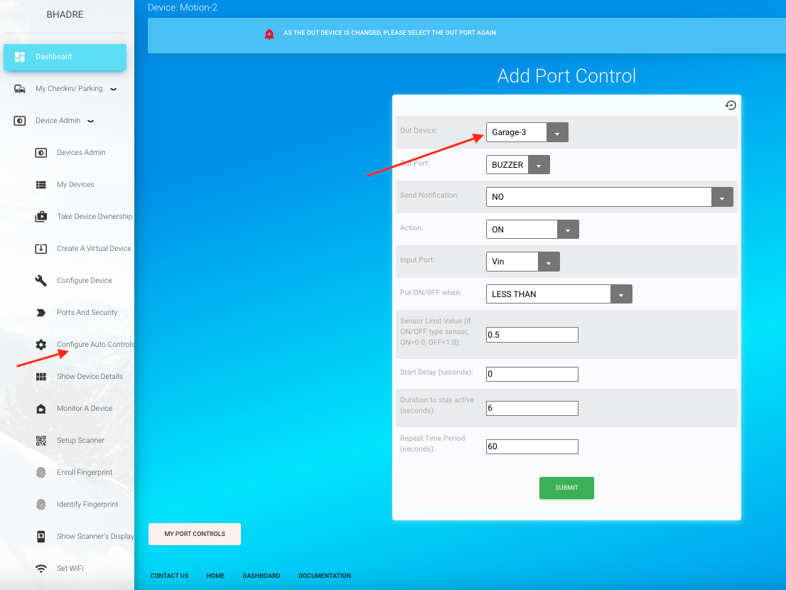
Let us see, for example, how to configure the device such that its output port is automatically put ON when the analog voltage read from Vin is greater than or equal to 1.0Volts, and it gets put OFF when the voltage is less than 1.0Volts. To configure this automatic control, click on 'Configure Auto controls' under Device admin in the Dashboard menu. As mentioned in the previous section, it may prompt you to choose device if you have more than one device. Once selected, it will come to portcontrols page displaying all the portcontrols that you have configured on this device so far. Click on 'ADD INPUT BASED PORT CONTROL' on this page. That will take you to a page similar to Fig 47.
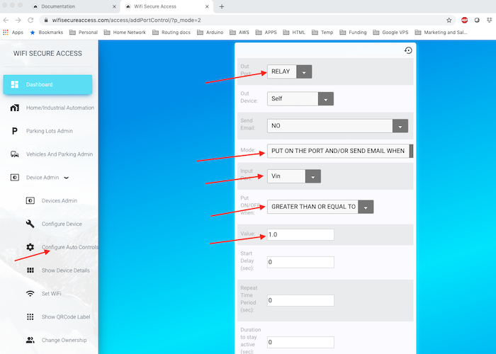
Similar to what we did when configuring periodic port control, select the various fields in this form. For our example, Choose 'Self' for the 'Out Device' and select RELAY for output port. In fact, this system has capability to activate a port on another device when sensor condition on this device are met. We will discuss that in the next subsection. Here, for our example, select 'Self' for this field. In the 'Send Notification' field, select what kind of notification you want it to send when the condition is met. If you do not want it to send any notification, select No.
Choose the 'Action' in the next field. The action is what you want it to do when the condition is met. The choices are ON, OFF, Enable Device, Disable Device, or Notification only.
Choose the input sensor in the field 'Input Port'. Depending on what you have connected to D6, and D7, you will be presented with the available choices. For this example, select Vin.
In the next field, you have to choose a logical comparator, either 'LESS THAN' or 'GREATER THAN OR EQUAL TO'. For our example select 'GREATER THAN OR EQUAL TO'. This is for the comparison of the sensed value with the Sensor Limit Value.
The device will compare the sensed value from the input sensor Limit Value to make a decision on activating the output port.
.
In the field 'Sensor Limit Value', enter a value. For our example, enter 1.0.
This means that the device will continuously read Vin and compare it with 1.0Volts. If the value at Vin is greater than or equal to 1.0, the condition for activation of the output port is met.
There are three more field in this form. They are to be filled if the output port must be put off after a duration even if the input condition remains met, and whether the output port must be put on again in a repeat cycle if the condition remains met.
For our example here, let us leave those fields blank and press submit.
If every entry is correct, it will configure the device and will show you portcontrols page of this device showing all the portcontrols that you have configured so far as shown in Fig 48. You may have to scroll the form right to see all the columns of this port control.
You have just one input based port control. That port control will put on RELAY when Vin is 1.0volts or more. Relay will remain ON so long as Vin is greater than or equal to 1.0. Relay will be put OFF when Vin is less that 1.0Volts. You can test this on the device by applying voltage at Vin.
The above control has some drawbacks when the Vin fluctuates rapidly around 1.0Volts. The Relay will keep on putting ON and OFF if Vin fluctuates around 1.0Volts. In systems where you do not want such things to happen, you can add a separate portcontrol to put the relay off. In other words, say, you want the relay to be put on when Vin greater than or equal to 1.0Volts, but once it is ON, you want relay to be OFF only when Vin is less than 0.5Volts.. This can be done by adding one more portcontrol for RELAY. Click on 'ADD INPUT BASED PORT CONTROL' once more and add another port control to put RELAY OFF when Vin is less that 0.5volts as shown in Fig 49.
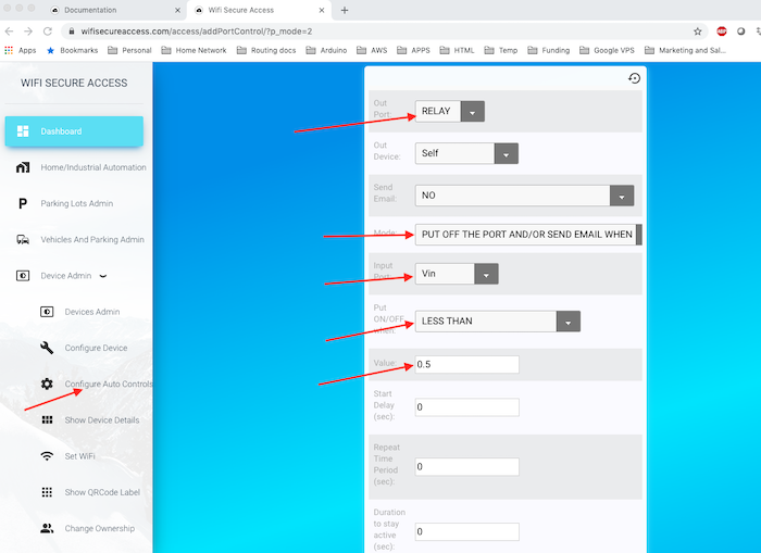
Enter the values as shown in Fig 49 above and press Submit. It will then show you portcontrol page similar to Fig 50 with two portcontrols for RELAY. The first one is to put RELAY ON and the second one is to put RELAY OFF.
You may test this now by applying voltages at Vin. You will see that the Relay comes ON when Vin is greater than or equal to 1.0. It will stay ON until Vin goes below 0.5Volts.
Note: Make a note of the difference between having just one portcontrol to put the relay ON and having separate portcontrols for putting relay ON and OFF respectively.
As mentioned before, you have three other fields in an input-based portcontrol They are 'Start Delay', 'Repeat Time period' and "Duration to stay active'. These fields can be used if you want the relay to stay active only for a fixed duration when activated and repeat this periodically, instead of keeping it on whenever the input conditions are met. If you want to wait for a delay time to activate relay after the input condition is met, enter that delay time in seconds in 'Start Delay' field.
For example, if you enter 10 seconds for 'Start Delay', delay will be activated only 10 seconds after the input condition is met. And, if you set a duration of, say, 60, the relay will get put off automatically after 60 seconds even if input condition remains met. And, if you enter 60 seconds for "Repeat Time Period', relay will be put on again after 60 seconds. This cycle will repeat until input condition for putting OFF relay is met.
You can generate input based port controls on any output port as per the steps outlined above. You can use any types of inputs connected to the input ports. They can be limit switches, ultrasound sensors, motion sensors, analog inputs, DHT11 temperature/humidity sensor, DS18B20 temperature sensor and so on.
Note: If you are using ON/OFF type sensor, keep in mind that the value read is either 0.0 or 1.0. The the Value field should be either 1.0 (OFF) or 0.0 (ON) when adding an input based port control. If you enter anything above 1.0 for Value when the sensor is an On/OFF type, it will automatically set it as 1.0. Similarly, if you enter less than 1.0 for Value, it will automatically reset it as 0.0..
4 Configuring One Device to Control Another Device
Our IOT system has the capability of controlling ports on remote devices based on the conditions sensed by another device. You can configure a device to control another device. You set the port controls of a device such that when a condition on inputs is met, an output port of another remote device is activated. Both devices must be owned by you to make this type of port control. Configuration is the same as described in the previous sections, except that when choosing Out device, choose the device whose Output port you want to control, instead of 'Self'. Available devices will be seen in the drop down selections.
If you own two devices, try setting this and try testing it.
5 Configure a device to activate Several Others
You can configure a device such that when it is activated (either turned ON or turned OFF), several other devices sitting remotely arec activated simultaneously. For example, when you open the front door, you can have several selected lights in the house or building or office to come ON automatically. Or, when you press one switch at the front of a building, all lights and selected equipments come ON automatically. This is all achieved without the need to do any additional wiring. Note: In order to get this functionality, all other devices must be connected through Bhadre's controllers or switches.
To configure this, go to Devices Admin under Dashboard. Then click on "paired devices" memu. In the form that opens up, select your device on which you want to have this control. If this selected device has mulitple ports, you will be prompted to select the port. If you leave the port as None, that means any port. That will open up a page asking you to select the other device and its port that must be activated simultaneously. Leave the port as None and press Smbit. If that selected device is a switch with multiple ports, you can now select its port. If you leave a port as None, it will activate all its ports. Once selected, press submit. Repeat this to add more devies that nust be activated simultaneously.
Once this configuration os completed, test by activating the main device and see if all other devices are simultaneouly getting activated