Cabling External Sensors to Bhadre Controllers
You can also connect any external sensors to this controller such a DHT11 or DS18B20 temperature sensors, or any analog sensors, or any other ON/OFF type of sensords.
If you have purchased a sdnsor from Bhadre, it already comes with an internal sensor already wired to the input ports. So, you cannot cable any external sensors to thos ports unless you unplug the iternal sensors. You can refer to the documentation of the sensor to know what internal sensor is pre-wired to what ports of the controller.
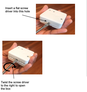
To connect anything external to it, or to replace the motion sensor it already has, you need to open the box of this device. To open the box and to access the internal green connector, do as shown in the picture below
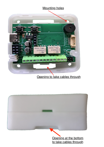
The PCB inside the box depends on the type of controller that you have bought. You can see more details of that controller in the document correspondiong to that. A picture of the PCB and the pin assignments of its green connector will also be seen in that document. Here are some of those pictures of the controller PCB.
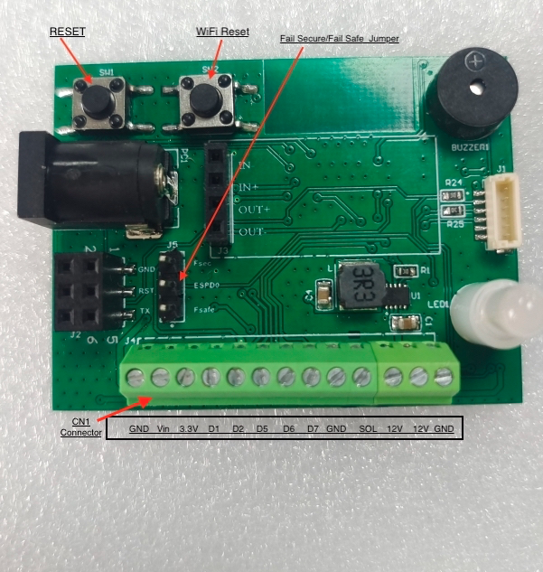
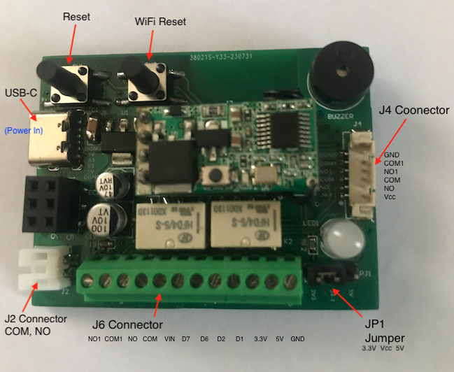
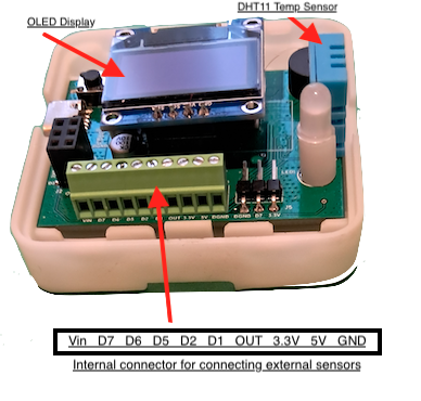
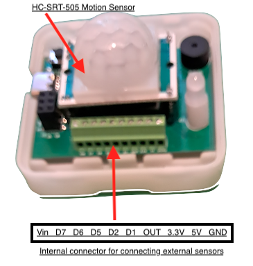
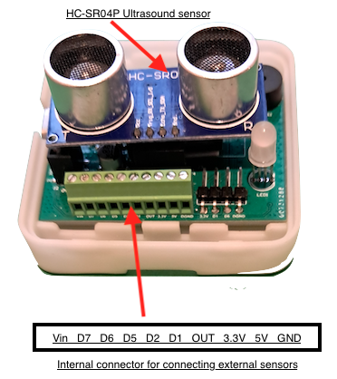
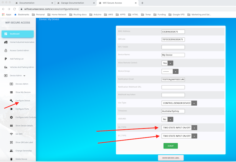
The green connector is the one to connect any external sensors. Its pin assignments are shown in the picture above. Once a sensor is connected, you need to re-configure the device and select what is connected to D6 and D7. To do that go to https://bhadre.com and click on Admin Dashboard. It may prompt you to login if you are not logged in already. On this dasboard menu, click on Devices Admin. Then click on Configure Device. In the form that opens, choose the D6-Type and D7-Type from the pulldown menu and press submit.
You can then use these sensors in configuring Automatic Controls.
1 Cabling ON/OFF type sensors
If we are interested in reading the status of an ON/OF switch such as limit switch or any other sensors such as motion detectors that gives ON or OFF output, they can be connected to our smart device for reading its status and to take any action. An ON/OFF sensor can be connected either to D6 or D7 inputs of the smart device. Refer Fig 19.
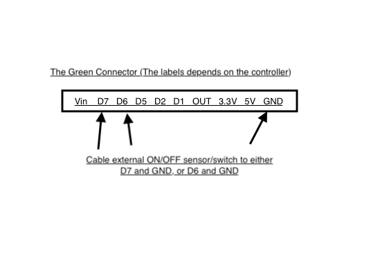
Connect the ON/OFF sensor between D6 (or D7) and GND. If it is an ON/OFF switch, connect its one terminal to D6 (or D7) and the other terminal to GND on connector J5 of the smart device. If you have a sensor such as PIR motion sensor, connect the OUT of the PIR motion sensor to D6 (or D7) and connect GND of the sensor to GND terminal of the device and connect 3.3V(VCC) of the sensor to 3V3 pin of the smart device. After doing this cabling, put the device ON. Then on a browser or in the app on a smart phone, click on 'Configure Device' under Device admin in Dashboard. On this window, make sure that D6_type as well as D7_Type are both selected as TWO STATE INPUT ON/OFF. If they are not in that state currently, select them and press submit.
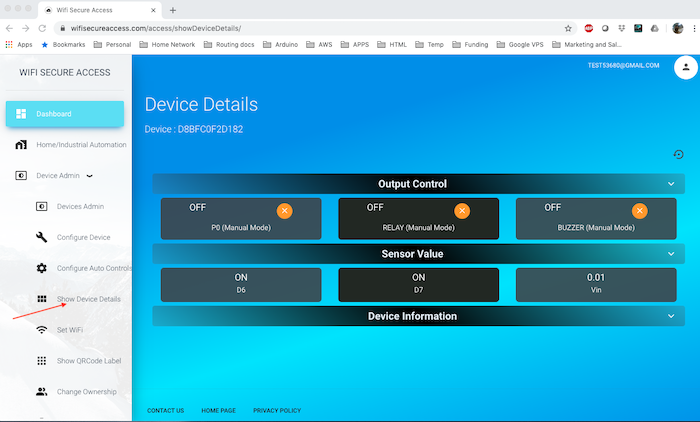
Then on a browser or in the app on a smart phone, click on 'Show Device Details' under 'Device Admin' in Dashboard menu. Then click on Sensor Values tab. You will see a window similar to Fig 20A.
The status of the sensors connected to D6 and D7 will be displayed here. If D6 or D7 is at 3.3V, it will display as OFF, and if it is at 0V, it will display as ON. If nothing is connected to D6 or D7, it will display as OFF (reverse logic).
In the document Configuring Automatic Controls you will learn how to use these sensor inputs for controlling any output ports or equipment connected to this device or any other device sitting remotely. We will also learn how to read these sensors and log the data periodically.
2 Cabling Analog Sensors
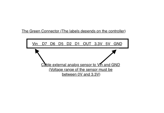
Any sensor which gives an analog output can be connected to this device. Some of the available smoke detectors or light sensors are examples of these type of analog sensors. Connect the analog output of the sensor to the Vin pin of connector J1 of this device with ground connected to GND. Please note that the voltage range of Vin is 0 through 3.3Volts. So, the analog output must be in this range. If not, you will have to modify the analog output using external circuits to convert the range between 0 and 3.3 Volts.
Once connected, click on 'Show Device Details' in the left menu bar under Device Admin. Then under Sensor Values, you will see the actual voltage sensed.
In the document Configuring Automatic Controls you will learn how to use these sensor inputs for controlling any output ports or equipment connected to this device or any other device sitting remotely. We will also learn how to read these sensors and log the data periodically.
sitting remotely.
In the document Integration with your other Apps and programs you will learn how to read these sensors and log the data periodically.
3 Cabling Ultrasound sensors
The device can be used to read HC-SR04 Distance Transducer Sensors. These sensors are low-cost sensors which are readily available in the market. You will find them on eBay and amazon.
Figure 22 shows how to connect this ultrasound sensor to the smart device. You can connect ultrasound sensor either to PJ3 connector or J1 connector on the controller. Both these connectors have D1 and D6 which are required to cable the ultrasound sensor. This connector has four pins (GND, D1, D6 3V3). Use a flat cable to connect D1 to 'Trig', D6 to 'Echo', GND to GND and 3V3 to VCC as marked in Fig 23.
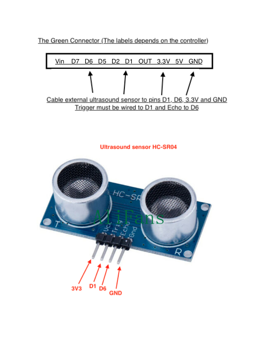
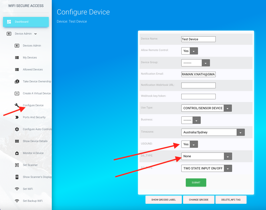
Once connected, click on 'Configure Device' in the left menu bar under Device Admin in Dasboard. Then select USOUND to 'YES' and D6_Type as None as shown in Fig 24. Then press Submit.
Now, you can see the distance read by the ultrasound sensor on the Device Details page. Click on 'Show Device details' in menu bar in the left under Device admin. Then click on sensor Values. You will see a page similar to Fig 25 with the current value read by the ultrasound sensor under U_SOUND.
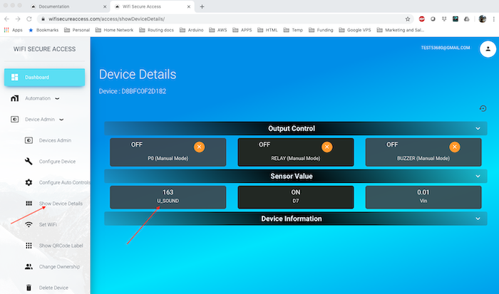
Refresh the page again to read again. Move the objects around ultrasound sensor and notice the actual distance measured. You need to refresh the page every time you move the sensor to display the new distance. We will see later in this documentation how all these can be automated to control anything depending on the inputs.
In the document Configuring Automatic Controls you will learn how to use these sensor inputs for controlling any output ports or equipment connected to this device or any other device sitting remotely. We will also learn how to read these sensors and log the data periodically.
sitting remotely.
Note: If you are interested in using this smart device for data monitoring and logging, as well as data analysis, you can read this data to your local computer using a json call. In the document Integration with your other Apps and programs we will provide sample python programs to read sensor values at regular intervals. You can then write your own program to analyse the data the way you want.
4 Cabling Motion Sensors
The Bhadre controllers can be used for reading motion sensors and take actions. Low-cost motion sensors are available through eBay or Amazon.
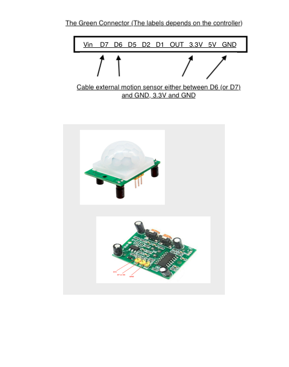
Fig 26 shows how to connect this motion sensor to the smart device. This motion sensor has three pins (GND, OUT, VCC). Connect VCC, OUT and GND of this sensor to 3V3, D7 and GND respectively on the green connector of the device. You can also use D6 or D7 on J1 connector. Motion sensor's OUT can be connected either to D6 or D7 of the smart device.
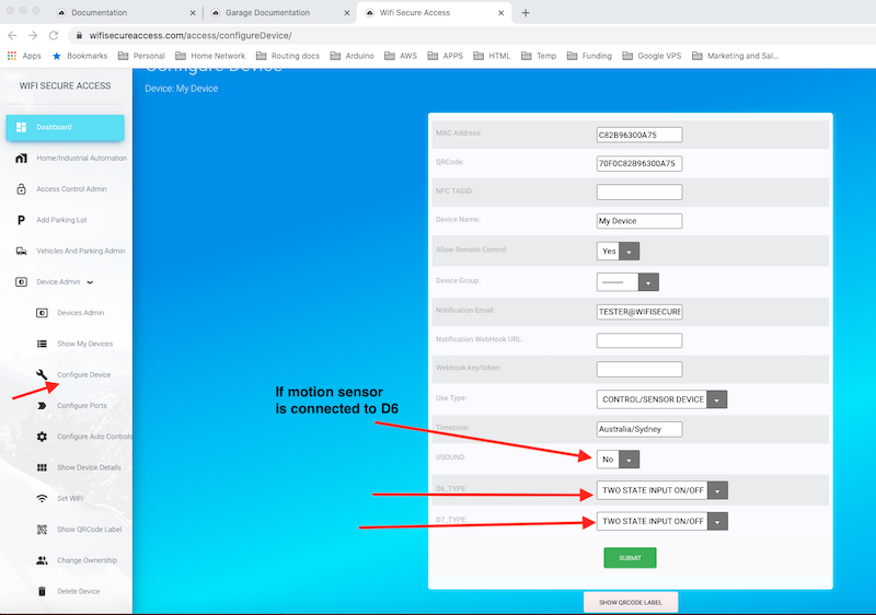
Once cabled, you need to configure the device. Click on 'Configure Device' in the menu bar on the left under Device Admin in Dashboard. Then select D7_Type as 'TWO STATE INPUT ON/OFF'. If you have connected motion sensor to D6, USOUND must be selected as None, and D6 as 'TWO STATE INPUT ON/OFF'.
Once connected, click on 'Show Device Details' under Device Admin in the menu bar on the left. In Sensor Values, you will see the state of the motion sensor. If motion is detected, and if you have connected motion sensor to D7, you will see D7 displayed as ON. In later sections of this documentation, we will describe how the devices can be configured to take any automatic actions when motion is detected.
5 Cabling DHT11 Temperature Humidity Sensor
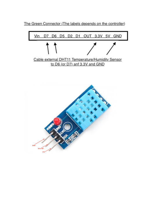
DHT11 temperature/Humidity sensor is a low cost sensor for reading ambient temperature and humidity. This sensor is available to buy. You can search in eBay or amazon or do a google search to source it.
Connect this sensor to the device as shown in Fig 29 and Fig 30.
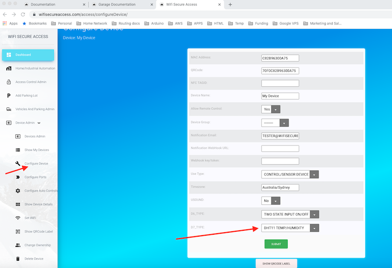
Now, in order to use this, you need to configure the device. Click on 'Configure Device' under Device Admin in the Dashboard menu. If you have connected the sensor to D6, select USOUND as None and D6_Type as 'DHT11/TEMP/HUMIDITY'. If you have connected to D7, select D7_Type as 'DHT11/TEMP/HUMIDITY'. Then press Submit.
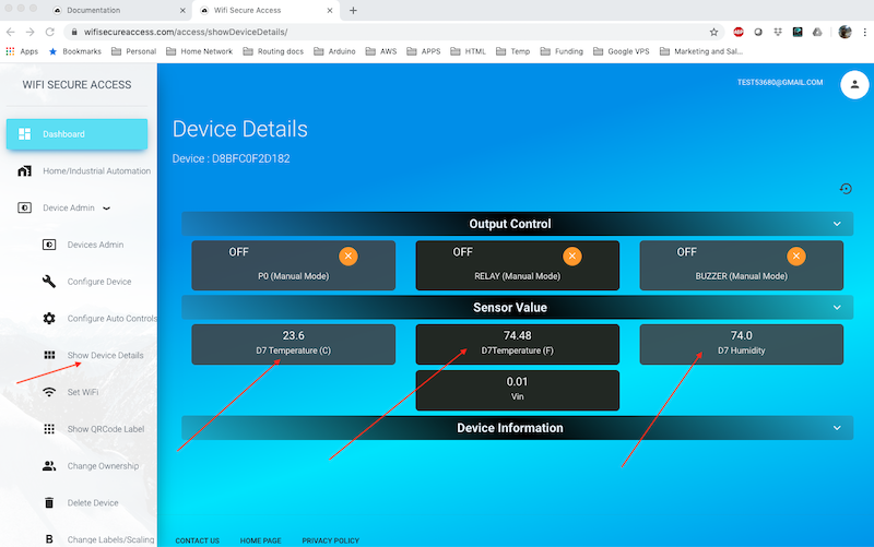
Once set correctly, click on 'Show Device Details' under Device Admin in the menu bar on the left in Dashboard. You will see the temperature and humidity read by the sensor under Sensor Values.
In the document Configuring Automatic Controls you will learn how to use these sensor inputs for controlling any output ports or equipment connected to this device or any other device sitting remotely. We will also learn how to read these sensors and log the data periodically.
sitting remotely.
Note: If you are interested in using this smart device for data monitoring and logging, as well as data analysis, you can read this data to your local computer using a json call. In the document Integration with your other Apps and programs we will provide sample python programs to read sensor values at regular intervals. You can then write your own program to analyse the data the way you want.
6 Cabling DS18B20 Temperature Sensor
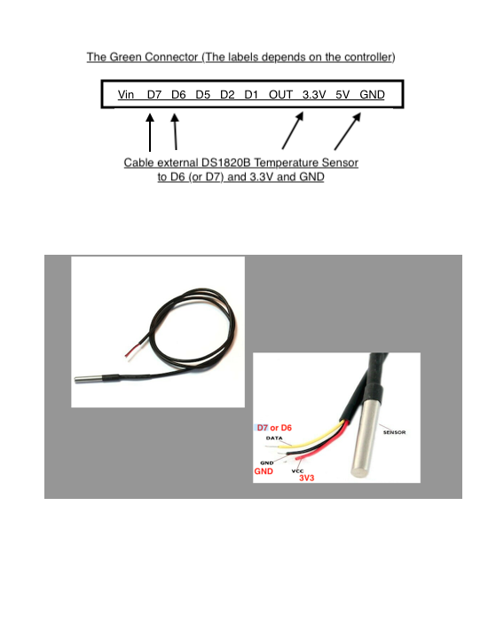
DS18B20 temperature sensor can also be used with our smart device. This can be procured through eBay or Amazon or any other source of your preference.
Connect this sensor to the device as shown in Fig 33.
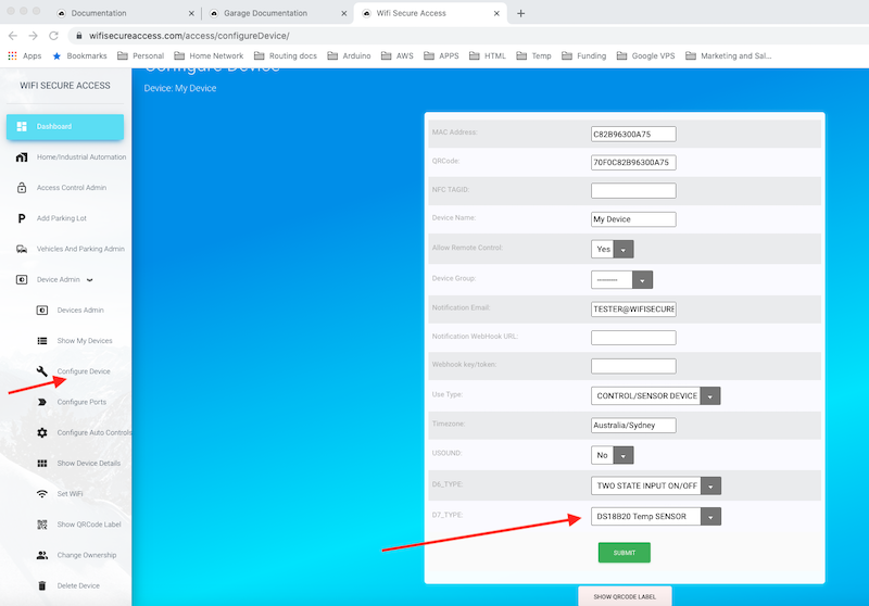
Now, in order to use this, you need to configure the device. Click on 'Configure Device' under Device Admin in the Dashboard menu. If you have connected the sensor to D6, select USOUND as None and D6_Type as 'DS18B20 Temp SENSOR'. If you have connected to D7, select D7_Type as 'DS18B20 Temp SENSOR'. Then press Submit.
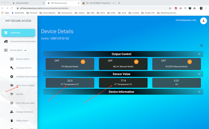
Once set correctly, click on 'Show Device Details' under Device Admin in Dashboard menu. You will see the temperature read by the sensor under Sensor Values.
In the document Configuring Automatic Controls you will learn how to use these sensor inputs for controlling any output ports or equipment connected to this device or any other device sitting remotely. We will also learn how to read these sensors and log the data periodically.
sitting remotely.
Note: If you are interested in using this smart device for data monitoring and logging, as well as data analysis, you can read this data to your local computer using a json call. In the document Integration with your other Apps and programs we will provide sample python programs to read sensor values at regular intervals. You can then write your own program to analyse the data the way you want.