Ultrasdound Sensor/Controller
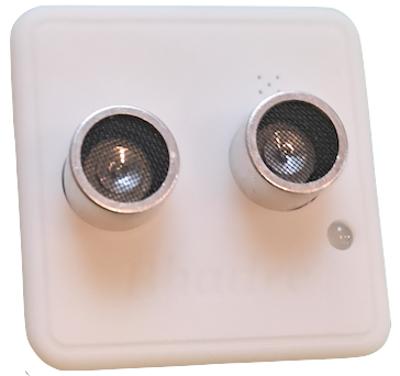
Bhadre's Ultrasound Sensor/Controller is a cloud based sensor/controller. It can be used for sensing a motion and to control any other devices when ultrasound sensor detects an object within a distance from it. It can be configured to control any external equipments connected either to it or to any Bhadre's controller located anywhere.
This document explains how this Ultradsound Sensor/Controller can be installed and configured to meet your needs.
1 Ultrasound Sensor/Controller
2 Installation
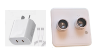
Ultrasound Sensor/controller is as simple as mounting the sensor on a wall or wherever convenient. You can use a double-sided tape or screws.You need a power outlet next to it to apply 5V power. You can either use a 5V USB-C power adapter (the same as the one used for smart phones), or a 5V power supply and wire it to the +5V and GND terminals on the green connector on the PCB inside the box of the controller.
3 Initial Setup and Common Configurations
In order to use this Ultrasound sensor/controller, it needs some initial minimum configuration. These initial configurations are common to most of the devices of Bhadre. Click here to see the instructions on doing the initial configurations of this device4 Configuring Automatic Controls
Ultrasound sensor/controller can be configured to control any equipment connected to any other Badre's controller. It can be an alarm, or a doof bell, or anything else. It can be configured such that when it detects an object within a specified distance from it, the equipment can be turned ON. The equipment can be a gate or door as well. These equipment can be sitting anywhere. No wiring is needed.
To configure automatic controls, refer to the document "Configuring Automatic Controls"
5 Connecting external sensors
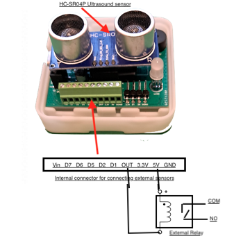
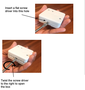
You can also connect any external sensors to this controller such a DHT11 or DS18B20 temperature sensors, or any analog sensors, or any other ON/OFF type of sensords. By default, an ultrasound sensor is connected to it intenally to D1 and D6 input of the controller. You can unplug that, if you want internal motion sensor and want to use that D7 port for connecting any external sensors. In addition to D7 port, there are a few other ports to which external sensors can be cabled.To connect anything external to it, or to replace the ultrasound sensor it already has, you need to open the box of this device. To open the box and to access the internal green connector, do as shown in the picture below
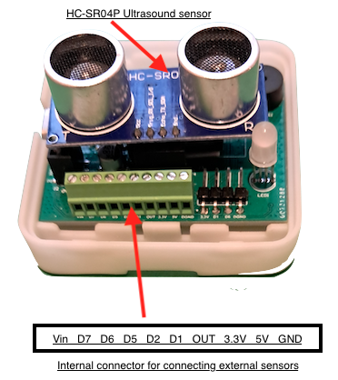
The green connector is the one to connect any external sensors. Its pin assignments are shown in the picture above. iKeep in m ind that internal ultrasound sensor is connected to D1 and D6 and so, you cannot connect anything to these two pins unlress you unplug the internal ultrasound sensor. Vin and D7 are available for cabling external sensors. Refer to the document Cabling External Sensors to Bhadre Controllers to know how external sensors can be cabled to this. Once a sensor is connected, you need to re-configure the device and select what is connected to D6 and D7. To do that go to https://bhadre.com and click on Admin Dashboard. It may prompt you to login if you are not logged in already. On this dasboard menu, click on Devices Admin. Then click on Configure Device. In the form that opens, choose the D6-Type and D7-Type from the pulldown menu and press submit.
You can then use these sensors in configuring Automatic Controls.
6 Connecting external ON/OFF Equipment
One can also wire an external eqipment to this ultrasound board. The external equipment can be a low-voltage(5V) low-power devices such as a 5V-electromagnetic coil of a relay (less than 900ma), or LEDs, or a relay that operates any equipment such as ac powered solenoid, coffee machine, and so on. Any such external ON/OFF equipment must be wired to the two terminals Out and +5V on the green connector on the PCB inside the box.