WiFiSecureAccess provides a dedicated garage door controller that can be used with garages and similar gates only. It will not work for any other types of access control. Dedicated garage door opener is a smart controller that can be integrated with an existing garage door (or gate) controller to provide smartphone based access. With this integration, one can also use Google Home, Google Nest or alexa to operate the garage door or gate. The garage/gate can be operated from anywhere remote. One can also know the current status of the garage/gate (whether open or closed) from remote. Notifications can be configured to send notifications if the garage door/gate remains open for a long time. One can configure AutoClose such that the garage door/gate gets automatically closed after a pre-configured delay. Multiple users can be authorized to open/close the garage door/gate. The owner of the garage/gate can revoke this authorization any time. It is also possible to configure the door such that the authorization gets automatically revoked after a date/time. In addition, one can configure open and close times such that only between these times the authorized persons can access the garage door. It is also possible to set authorizations such that some people are allowed to use only during some specific time period on pre-configured days of the week. This documentation describes how the smart controller can be installed on an existing garage door/gate and how the smart device can be configured to meet all the needs.
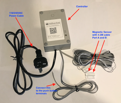
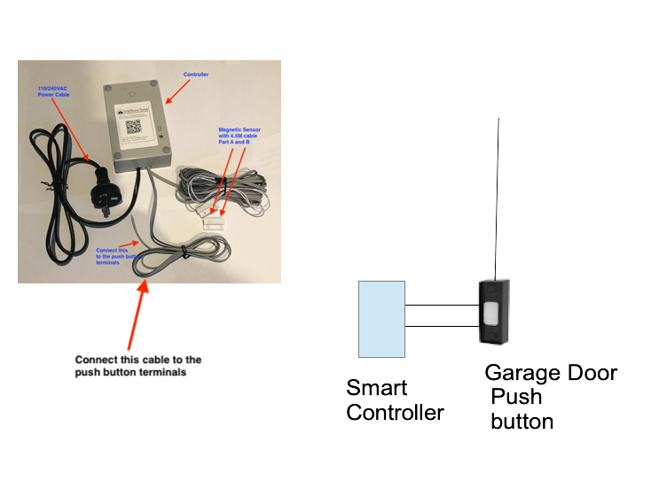
Fig 1: pre-wired and pre-configured garage door controller.
This smart device can be purchased either from eBay or from Amazon. It will be available through other sources in the future. Search for WifisecureAccess in eBay or Amazon.
Note: If you have purchased a dedicated garage door controller, it is to be used for garage doors or gates and not to be connected electric strikes on doors. To connect to electric strikes, you need to purchase our general-purpose access controller.
2.0 Installation of Hardware
In this section, we will describe how the smart controller can be wired and integrated to your existing garage door controller.
2.1 Integrating Smart controller to your existing garage door
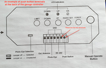
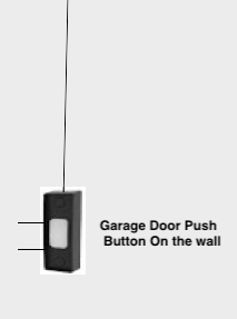
In order to integrate the smart controller to your garage door, you need to locate the two terminals of a manual push button on your existing garage door controller. There are plenty of manufactures of the garage door and, therefore, the controller of the garage door can come in various designs. However, all garage doors will have a manual switch (push button) to open/close. This switch may either be located on the PCB of the garage door controller, or it may be mounted on the wall or elsewhere in the garage. On some garage door controllers, you may find two terminals on a terminal block on the main controller marked as 'Push Button'. Here are some example pictures:
Fig 2: An example of a terminal block on the back of a garage door controller
Fig 2A: Another view of an example of a terminal block on the back of a garage door controller
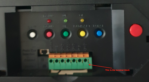
Here is another garage door controller from another manufacturer:
Fig 2B: Another view of an example of a terminal block on the back of a garage door controller
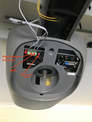
Or, in some cases, you may find a push button on the wall.
Fig 2C: Another view of an example of a terminal block on the back of a garage door controller
You can cable the smart controller to either the push button terminals on the main controller, or to the two terminals inside the push button on the wall. Test manually before cabling the smart controller to the push button terminals to confirm that this is compatible. To test it manually, short between the two terminals using a bare wire. You should be seeing the garage door either opens or closes. If so, this is compatible to the WiFiSecureAccess smart controller
If the garage door is compatible, cable the WifiSecureAccess smart controller to the push button terminals of the garage door. Refer to Fig 1 to see which wire from the smart controller is to be cabled to the push button terminals. Mount the controller anywhere convenient, preferably close to the pushbutton terminals (either on the wall, or near the terminal blocks on the garage controller). Note: The controller unit has a double-sided mounting tape at its back. So, you can mount it anywhere convenient, and no screw is required.
Fig 2D: Cable Smart device to the push button terminals of the existing garage door controller
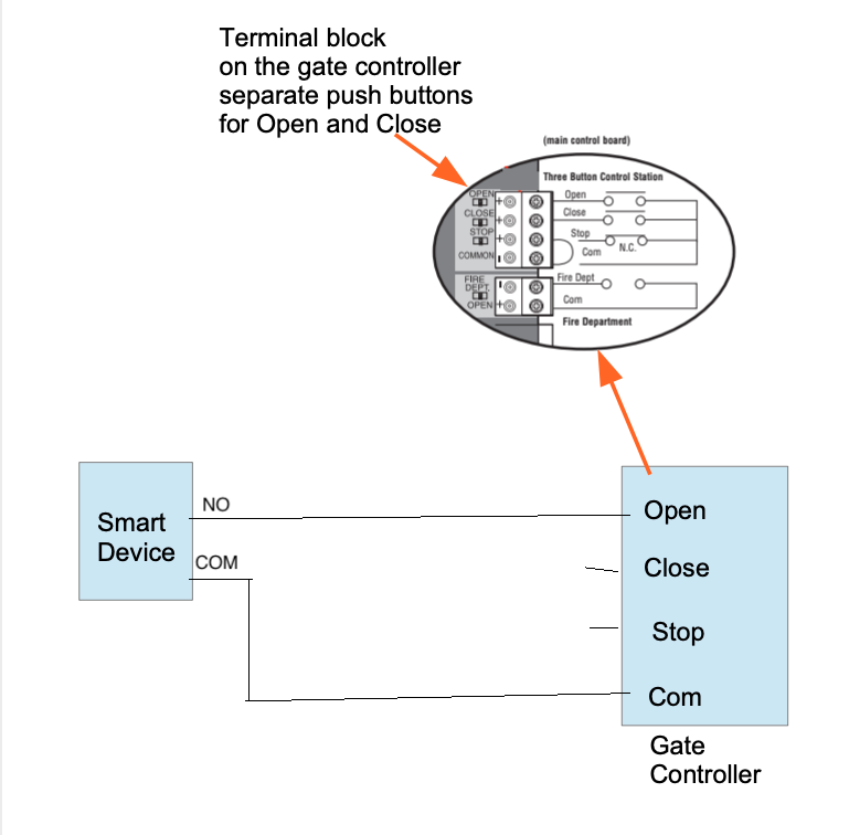
Gates with two push buttons - one for Opening and another for Closing
There are some gates with two separate manual push buttons - one for opening and another for closing. In most of those cases, the gate's controller usually closes the gate automatically a few seconds after it is opened. So, smart device needs to be cabled to the Open terminals of the gate controller.
Fig 2D1: Cabling of the device to a gate with two push buttons
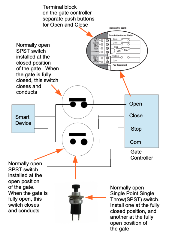
However, if you want the smart device to open as well as close that type of gate, the cabling of the smart device to the controller of that gate has to be done differently. To interface the WiFiSecureAccess smart device to that type of gates, you need to install two normally open Single Point Single Throw (SPST) switches on those gates. One is to be installed such that the switch closes and conducts when the gate is in fully closed position. Another SPST switch is to be installed such that it closes and conducts when the gate is in fully open position. Then cable the WiFiSecureAccess smart device through these two SPST switches as shown in the figure below. In this figure, the picture of the gate controller board is from the installation manual of a Lift Master gate available in USA. For any other similar gates, look for these Open and Close terminals on its controller board.
Note: It is assumed that the controller of the gate is such that it fully closes the gate when its Close push button is pressed and released without stopping the gate in between. Similarly, it is assumed that the controller opens the gate fully without stopping in between when the Open push button is pressed and released. If the gate is stuck in between, the controller of the gate must have the needed mechanism on its own to bring the gate either to a fully open position or a fully closed position. The Wifisecureaccess device will not be able to do that by giving commands when the gate is stuck in between
Fig 2D2: Cabling of the device to a gate with two push buttons
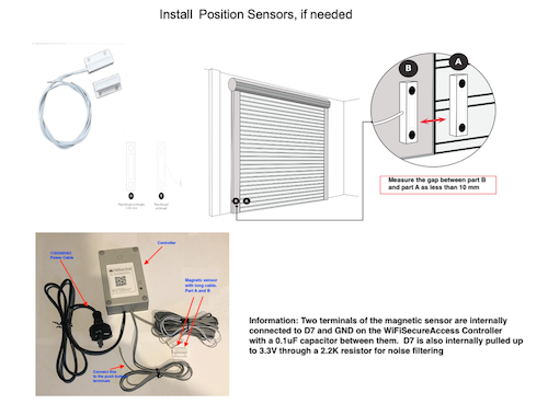
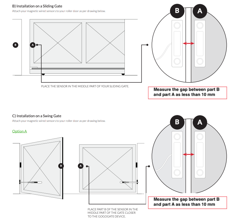
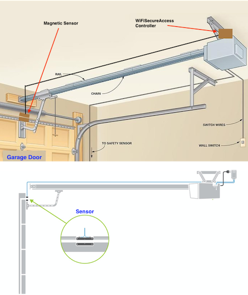
2.2 Installling Magnetic Sensor
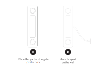
Next, install the magnetic sensor. This is optional. If you install this sensor, you can know from remote whether or not the garage is currently open or closed. This will also help sending alarm notifications. The pre-wired WiFiSecureAccess smart controller comes with this sensor. It has a long cable. The cable can be extended to fit on your garage. Try not to extend this cable beyond 4.5 meters to avoid noise. If you do not need long cable, you may cut that cable short. The shorter the cable, the better to avoid noise in reading sensor. Install the sensor at a convenient position on the garage door such that the distance from that to the WiFiSecureAccess controller is not too long. Install as per your convenience such that the two parts (A and B) of the sensor align themselves (within 10mm space between them) when the garage is closed. If the gap is longer, there can be instances that it can read incorrect position of the garage door. Fix the part (Part B) with the cable on the fixed frame and the other one (part A) on the moving frame of the garage. The following are some pictures that will help you install this. Note: Both the parts of the magnetic sensor have double-sided mounting tape at their back. So, you can mount it anywhere convenient, and no screw is required.
Note: If you do not want the sensor, and if you are not interested in sending notifications, and knowing the current position of the garage door from remote, you may not install this. You can cut this cable off from the dedicated garage door controller that you purchased.
Fig 2E: Magnetic switch on the garage door
Fig 2F: Two parts of a magnetic switch
Fig 2G: Installing magnetic switch
Fig 2G_1: Installing magnetic switch (another example)
After installing the sensor, you need to test if it is working properly. In section 3.7 of this documentation, you will see how to check if the sensor is currently ON or OFF (Refer Fig 11). The sensor must be ON when the garage/gate is closed and OFF when it is open.
Next, enable the sensor in the configuration. Click on 'Ports and Security' under Device Admin in the dahboard menu. Select the device. In the opening page, select 'Yes' for the 'Door Sensor Connected' field. Then press Submit button.
PS: In order for it to use the sensor to detect the current position of the garage door, not only that you have to install the sensor, but also you have to set 'Yes' to the field 'Door Sensor Connected' in the 'Ports and security' settings of this device.
If the device is installed on a door with electric strike that has Status sensor built in, then you do not need an external magnetic sensor. You can cable the two wires of the status sensor of the elecxtric strike to D7 and GND terminal of the controller.
If sensor is installed and enabled. you can also enable notifications as explained in section 3.14 of this documentation.
Note:The garage door can be operated even without the sensor. As mentioned earlier, the sensor helps in knowing the current position of the garage door (whether open or closed) from remote accurately. You can also enable sending notifications if the garage remains open for a long time. Sending notifications are possible only if the sensor is installed. If you do not want the sensor installed, you may remove the sensor and the cable from the WiFiSecureAccess smart controller. You can either cut off that cable, or you may open the smart controller and remove the cabling. The following pictures show the inside cabling of the WiFiSecureaccess smart controller.
Fig 2H: Inside view of the Garage Door Controller
Fig 2I: Inside view of the Garage Door Controller
2.3 Applying Power to the Controller
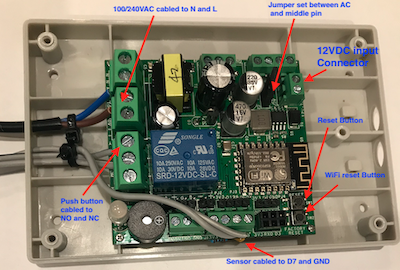
The controller can take either 110VAC power, or 240VAC, or 12VDC power. Depending on what power is available at the location where you are installing the controller, you connect any one of the power source to the controller. Fig 2I shows the internal connectors within the smart controller. The controller comes with ac AC cord cabled to the 110/240VAC connector within the device, and the internal jumper set to 110/240VAC. So, if you are using either 110VAC or 240VAC, you do not have to do anything internal to the box. Just connect the power plug of the controller to an AC socket on the wall. However, if you want to use 12VDC power instead of the 110/240VAC power, you have to open the plastic box of the controller and remove the AC power cord. Then connect 12VDC to the 12VDC connector shown in the above picture. If you do so, place the jumper between DC and the middle pin. Refer to Fig 2I to identify the appropriate connector and jumper.
Once all the installation and cabling are completed, power on the device by plugging its power cord to a 110/240VAC socket (or 12VDC, if you have re-cabled the device for 12VDC power).
3 Setup and Configuration
In this section, we will describe how to set up the device and how to configure it so that it works as per your requirements..
3.1 Setting up the App on your Smart Phone
If you have not downloaded the wifisecureaccess app yet, please download it to your smartphone now.
Search for wifisecureaccess in either Apple Store or Google Play store.
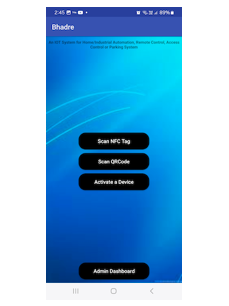
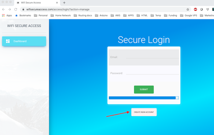
Once downloaded, open the app and press Admin Dashboard. It will prompt you to enter your username and password to login.
If you have not registered yet with https://wifisecureaccess.com, press 'Create NEW Account' button on this page and register.
Fig 3: App's opening page
Fig 3A: Login Page
Fig 3B: Register (Create a new account)
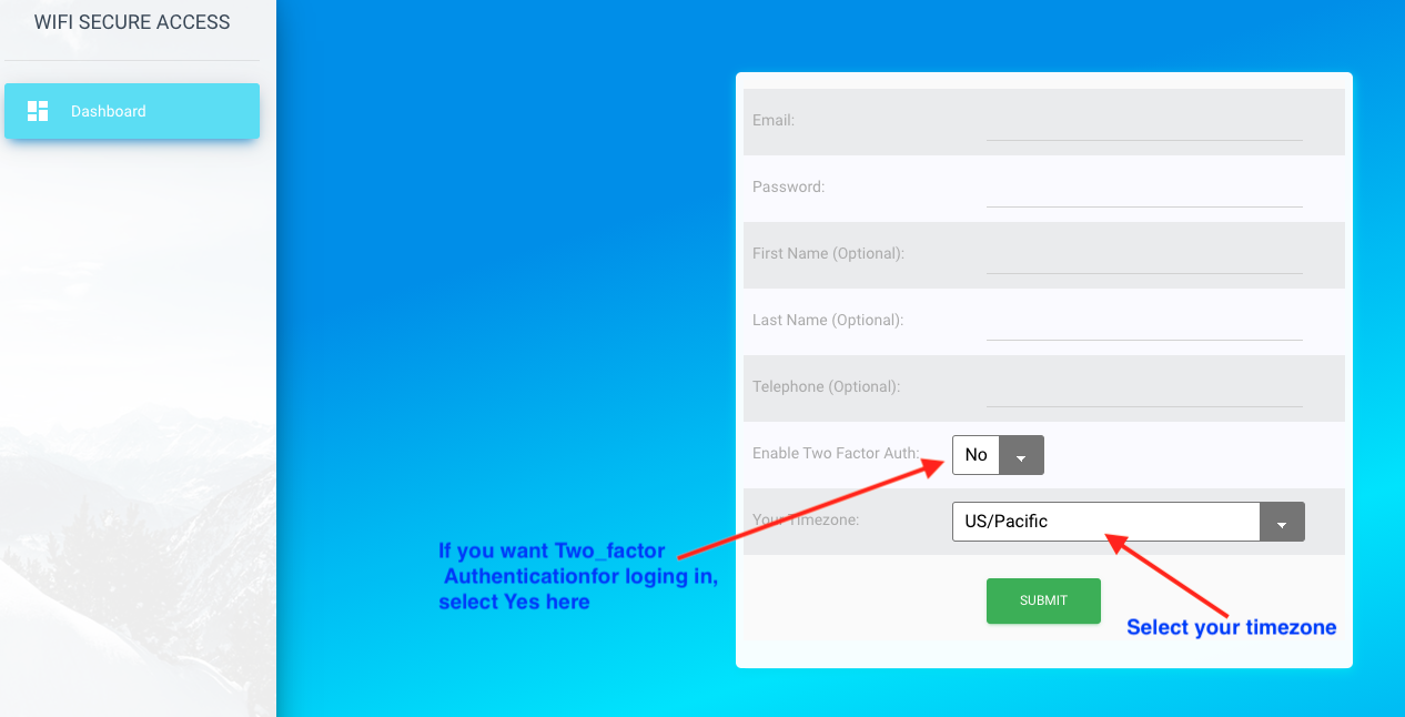
Follow the prompts and instructions. It needs your email address as user name. You need to set your password. first name, last name and telephone numbers are optional.
Password must have at least 8 characters (maximum 20 characters) and it must contain at least one lower case letter, one upper case letter, one numeric. The system will prompt you for your email verification.
The system uses email address as your username.
It also uses it to send notifications of events in the device, if you have configured the device to send you notifications.
The other two fields "Enable Two Factor Auth' and 'Timezone' will be defaulted to 'No' and 'US/Pacific' respectively. You can enable Two Factor Authentication by selecting 'Yes' for this field, if you want to. When selected 'Yes', a confirmation code will be sent to your email whenever you try to login. This is an additional layer of security for your account. The timezone is your timezone. Select it from the pull-down menu. The default is US/Pacific. Setting this to your timezone will help the system display the times of all your activity in your local time. All these parameters can be changed any time later by clicking 'My Profile' under 'User Admin" in the Dashboard.
Please keep your password confidential to make sure that the device is used by authorised persons only.
Note: The steps of setting up the device and configuring it can be done either using a smart phone or using a computer.
On a computer, you can open a browser and go to https://wifisecureaccess.com/access/index. It will prompt you to log in.
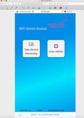
On a smartphone, open the wifisecureaccess app and press on Admin Dashboard in the main scanning page to get to the dashboard.
We recommend that you use a computer for all initial setup and configurations.
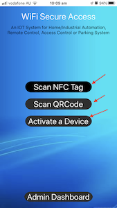
However, use your smart phone when you want to activate a device or its ports from remote, or when you need to scan its QR Code or NFC Tag, or when you want to use Google home assistant or Amazon Alexa.
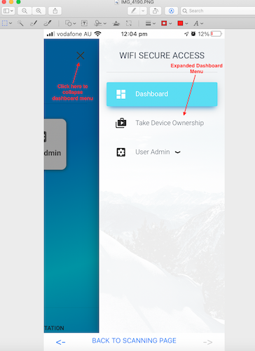
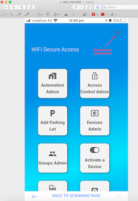
If you are using a smart phone to register, you will see a page similar to Fig 3C. Or, any time in the future, if you open the app and click on the Admin Dashboard, the same display will be shown. You will notice that all the admin menu is collapsed. To see the admin menu, click on the three lines at the top right corner of this page as shown in Fig 3C and 3D.
Fig 3C: Dashboard Menu on Smartphone (collapsed)
Fig 3D: Dashboard Menu on Smast Phone
3.2 Setting WiFi of the Device
There are two ways of setting the WiFi of the device
Using the hotspot of your smart phone
Setting the device as a web server and using a browser (Chrome preferred) on your computer or smart phone. Refer to Section 3.5 of this documentation for this method.
Using the HotSpot on your smart phone
If this is a brand new device, its WiFi has been factory reset to the following:
Upon factory reset, the device listens on a WiFi (2.4G) with the following ssid and password:
SSID : MyPhone Password: 12345678
So, when the device is powered ON, it is trying to join this WiFi. Therefore, in order to initially connect to WiFi, you need to setup a mobile hotspot on your smart phone temporarily to this SSID and password so that the device gets connected to internet which will enable you to change its WiFi. Note: (The device is not capable of 5G and so, WiFi must be 2.4G.)
If you are using iPhone, change its Personal hotspot WiFi settings to match the above and put Personal hotspot ON. To change your iphone's SSID, you need to change the name of your phone to MyPhone. This can be done in settings → General → About → Name. To change password, Settings → Personal Hotspot → Wi_Fi Password. Once changed, click on Allow Others to Join so that your Personal Hotspot is ON with this SSID and password. If you are using IPhone 12 and above, you will see a button there named "Maximize Capability". That is normally OFF. You need to turn that ON so that it will work on 2.4GHz.
If you are using an android phone, go to settings → Tethering and Mobile hotspot. Then click Mobile hotspot. Then click on the three dots at the top right and click 'Configure hotspot'. Then change the ssid and password of your mobile hotspot to 'MyPhone' and '12345678'. Note: If your smartphone is capable of 5G hotspot as well as 2.4G, make sure that 2.4G is set on the hotspot of your smartphone as the device is not capable of 5G. Also, check the Timeout settings of the hotspot. Set it such that it does not timeout too soon while you are using Hotspot. You can set it to Never time-out. After setting it, switch on your mobile hotspot (in the previous menu).
Note: Make sure that the mobile data on your smartphone is turned ON so that the device connected to your hotspot can get access to internet. Also, make sure that the Hotspot stays ON and never times out until you change the WiFi of the device as per the steps in Sections 3.3 and 3.4. Your mobile phone must not go into a sleep mode until you change the wifi of your device. For this initial setup, it is important that the device gets connection to internet through the hotspot on your smartphone. If the LED stays flashing blue, that means that it is unable to join the WiFi. If you observe the LED either stays flashing blue with occasional RED, it means that it is unable to connect to the internet after joining WiFi.
Once the personal Hotspot is ON, put on the device, if it is not already ON. You will notice that the device will join that WiFi and connect to internet. You will see in a few seconds that the LED changes colour to RED, and staying RED. If that is not happening, make sure that your personal Hotspot is configured correctly and that it is ON. If this is not happening, there is a problem with the WiFi. You can do a factory reset of the device as explained in section 3.5 of this documentation and try again. If the device is still not joining WiFi, ask for help by Contacting us.
If the device is connected to WiFi and connected to internet, the LED will stay steady RED. Then, you need to take the ownership of this device as explained in section 3.3 below before you can set its WiFi.
3.3 Taking Ownership of the Device
There are two ways in which you can take the ownership of a new device that you just bought. One method is by scanning the QRCode of the device using your smartphone, and the other method is by using a browser on a computer. Before you proceed, make sure that you have turned on the device and it has joined the WiFi of the Hotspot of your smart phone, as explained in the previous section of this documentation.
In the first method. open wifisecureaccess app on your smartphone and go to Scanning page and press Scan QRCode button.
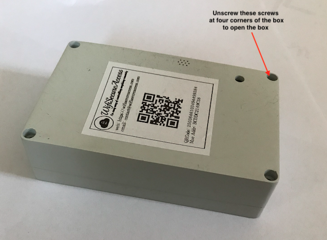
The camera will come ON. Scan the QR code of the device. The QRCode is on the label pasted on the box.
Then follow the prompt. You will be prompted to confirm the buzzer sound as well as the color of the LED a few times to make sure that you have this device in front of you, having connected to internet. If everything is correct, it will assign the ownership of this newly bought device to yourself.
For the second method, open https://wifisecureaccess.com and click on Dashboard. If you are already logged in, you can see a tab "Take Device Ownership" in the sidebar menu. If this is your first device, you will see that on the main page as well. Click on that, and follow the prompt. After getting the confirmation that the device is turned on and connected to internet through its WiFi, you will be prompted to enter the QRCode or Mac address of the device. On the label of the device, you will see either the mac address or the QRCode of the device. Enter it as shown on the label. Follow the rest of the prompts. If you respond to all the prompts correctly, the ownership of the device will be assigned to you and a popup window will appear confirming it.
Fig 6: Intial page view.
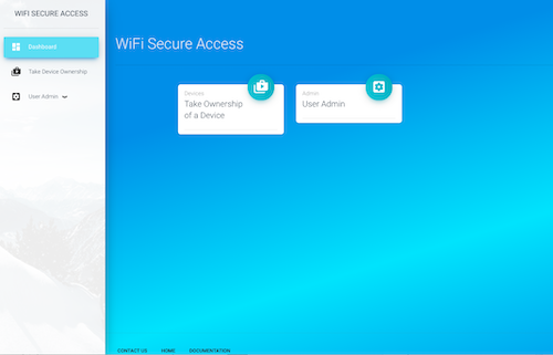
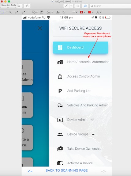
Once you have taken ownership of the device, your main dashboard page may look like the one shown in Fig 6A, if you are using a smartphone. And, if you expand the dashboard menu, you may see several options as shown in Fig 6B. If you are using a browser on a computer, you will see the dashboard menu on t
he left side bar.
Fig 6A: Dashboard view when you own a device
Fig 6B:Dashboard expanded menu when you own a device
Once the ownership is transferred, click on
'Access Control Admin' in the Dashboard menu. Then click on 'My Devices in Access Control'.
You will see your device listed there. If you have more than one device, all of them will be listed there. Once the device is assigned to you, nobody other than you will be able to configure it. In the later sections of this documentation, you will learn how to allow others to use this device. You will also learn how to configure this for your specific needs and how to use it.
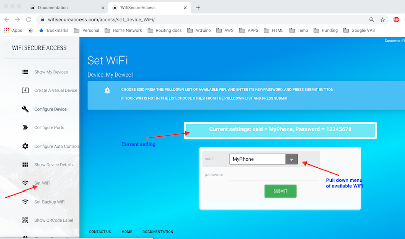
3.4 Changing WiFi of the Device
If the device is already connected to internet, you can change its WiFi any time as per the steps given here. In the dashboard menu, click on 'Devices Admin' to expand that menu. Then click on 'Set WiFi'. It will take you to a page where it will prompt you to enter the SSID and password of your WiFi. Make sure that the WiFi is 2.4G and not 5G. The device is not capable of 5G WiFi. If the device is running firmware version greater than 4.2, you will see a pulldown menu with all the available WiFi at that location. You can choose one, and enter its password. Once entered, click Submit. If successful, you will see the device restarting, the led blinks blue and then changes to steady Red. The device is now set to go and ready for use.
If you accidentally entered wrong ssid or password, or if the device is not getting connected to the new WiFi, you will hear double beep from the device. The device will then revert back to the previous ssid and will try connecting to it. If it is unsuccessful to connect to previous ssid, it will stay in that loop of attempting to connect, and LED will stay BLUE with occasional flashing. You can also do a factory reset as per the steps given in section 3.5 of this documentation. If you are running older firmwares, you will have to do a factory reset and repeat the steps given in section 3.2 and 3.4, if you entered wrong ssid and password.
If the device is still not connecting to your wifi, check the settings of your wifi router. Check if your router has set any limits on the nummber of devices that can connect
to it. Also check if its wireless mode is 802.11bgn, and its channel setting is Auto.
If the device was connected to the hotspot of your smartphone before changing wifi, try disabling hotspot on your smartphone now. If changing wifi was not successful, the LED will start blinking blue again after a few seconds.
Fig 8: Setting WiFi of the Device.
The device will remember the WiFi that you set and will connect to that WiFi hereafter whenever power cycled or reset.
If you have used mobile hotspot of your smartphone to get initial connection, you can switch that off now. You can change your smart phone's name and WiFi password to whatever they were initially.
After switching off the hotspot on your mobile phone, try resetting the device by pressing the reset button on the device.
If everything is set correctly, the device will restart and join the WiFi.
You will see LED blinking Blue while trying to join WiFi and then turning to red when successfully connected to WiFi and connected to internet and the cloud server.
If this is not happening, there is something wrong either with the ssid and password that you entered, or with your internet connection through WiFi. Make sure that the ssid and password that you set are that of a 2.4G wifi and not 5G. Make sure that your router has internet connection.
If anything has gone wrong, do a factory reset of WiFi as per the steps in section 3.5 of this documentation, and then try to set WiFi again.
3.5 Doing a Factory Reset of WiFi
The WiFi of this device can be reset to the factory reset any time, if you find a need for it. The factory reset WiFi is : ssid = MyPhone and password = 12345678.
If the device is running firmware version 4.2 and above, you can also set its WiFi using a browser on your computer or Smart Phone by doing a factory reset. This is another method of setting WiFi of the device. After doing a factory reset, follow the steps given here in this section to do so.
To do a factory reset, open the box of the device, and locate two push buttons marked Reset(SW1) and Factory Reset(SW2). Factory Reset Button is also called WiFi reset button. Refer to Fig 8A below to locate these push buttons. If the device is operating at 110V/240VAC, make sure not to touch any of the high voltage tracks or terminals to avoid getting shock. Then, press and hold SW2 (Factory Reset button). While holding it, press and release SW1 (Reset button). Keep holding Factory Reset button until the device restarts and LED changes to flashing blue/green. Then, LED will change to BLUE. At this moment, the ssid and password of the device has been reset to 'MyPhone' and '12345678' respectively. You can release holding the factory reset push button.
Fig 8A: Factory Reset Push button on the device.
If the device is running firmware version below 4.2, it will attempt to connect to wifi with SSID = MyPhone and password = 12345678. This is the method that we discussed in section 3.2 earlier in this documentation. You will see LED Blue and flashing occasionally. If you have enabled hotspot on your smartphone, the device will connect to it. and the LED will turn solid RED. If it is unable to connect, LED will flash blue occasionally and stay in that loop until connected. Refer to Section 3.2 of this documentation, and then follow section 3.3 to take ownership of the device and section 3.4 to change its wifi.
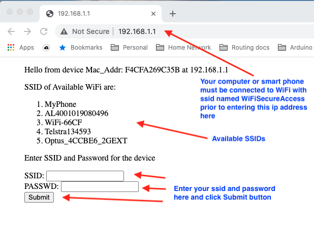
When the device is running firmware version 4.2 and above, the device will go into access point mode and operate as a web server. It will advertise an SSID = WiFiSecureAccess. LED will stay solid BLUE without any occasional blinking. Follow the steps below to set its wifi at this time. (Note: If you press reset push button again at this time, the device will change to the previous mode and will attempt to connect to factory reset ssid)
Setting WiFi of the device using a browser when the device is in web server mode
If your device is running firmware version 4.2 and above, factory reset will put the device in web server mode advertising an SSID = WiFiSecureAccess, and LED will stay solid BLUE without any occasional flashing. If you look at the available WiFi in your smart phone or computer, you will see this WiFiSecureAccess there. You will see this only after doing a factory reset of the device that is running firmware version 4.2 and above. Now, connect your computer or smart phone to this WiFi. Once your computer or smartphone is connected to this WiFi, open a browser (Chrome preferred) on your computer or smart phone and enter the ip address 192.168.1.1 in the url. You will see a window similar to the one shown in Fig 8B below.
Fig 8B: Setting WiFi using a browser.
On this page, it will list all the available SSIDs. Enter your SSID and Password and press Submit button. If your entry is correct, the device will set the WiFi of your device to that. Then it will try to connect to that wifi. You will see LED flashing occasionally BLUE. If it is able to connect to this wifi, you will see the LED changing to RED and staying RED (solid RED). If this is a brand new device, as a next step, you need to assign the ownership of this device as explained in section 3.3 of this documentation. If ownership is already assigned, the device is ready to be used.
If it is unable to connect, the device will beep twice (after a few seconds of attempts) and will revert back to the factory reset ssid (MyPhone). Then, it will try to connect to factory reset ssid. If so, follow the steps as explained in section 3.2, or do the factory reset again and enter the correct ssid and password.
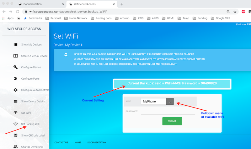
3.6 Setting a backup WiFi
If the device is running firmware version 4.2 and above, and if you have more than one WiFi at your premises, you can set up a backup WiFi on this device so that the device will switch over to the backup WiFi whenever the main wiFi fails. Unless you set a backup WiFi, the default backup wiFi is the main WiFi that you have set. If you want to set a backup WiFi, open the dashboard and click on 'Set Backup WiFi' under Device Admin. You will see a page similar to Fig 8C. Just like the way you set the main WiFi in section 3.4, this page shows all the available WiFi in a pull down menu. You can select one of those, or select 'Other ...' to set anything else. Once selected, press Submit.
If successful, the device saves this backup WiFi and will switch to this WiFi whenever the main WiFi fails with three attempts.
Fig 8C: Setting Backup WiFi
Note: If any time need arises, you can use your smartphone's hotspot as a WiFi connection to the device. If you do a factory reset (we called this 'WiFi Reset' a few times), the device resets its WiFi to ssid = MyPhone and password=12345678. Then, if you see LED staying in solid BLUE, press reset button again. You will see LED flashing BLUE. At this time, if you set the hotpot's ssid and password to this and enable hotspot on your phone, the device gets connected to internet. This feature becomes handy when all the configured WiFi fails.
3.7 Initial Configuration of the Device
Once the above configurations and installations are completed, the garage door is ready to be used using smartphone already without doing anything more, even though the current position of the garage door may not be reported correctly. You can now operate it either using the WiFiSecureAccess App on the smartphone, or by GoogleHome or Alexa. The garage door can now be discovered by GoogleHome as well as Alexa. Currently, the device is autoconfigured for garage with default settings. Those default settings are normally enough for normal usage of the garage door, if you are not interested in knowing the current position of the garage door from remote, and sending notifications. However, before you start using it, it is recommended to go through the various features that are described in the following sections of this document.
To start with, click on Devices admin in the dashboard menu. Then click on My Devices. You will see this device listed there. If this is your first garage controller, the name may be 'Garage'. If you have more than one device, all will be listed here.
Note: The pictures shown in this document are snapshots taken when using a computer. If you are doing this on a smartphone, your view will be similar, but without a dashboard menu at the left side. When using smart phone, to see the dashboard menu, you have to click on the three lines at the top right as shown in Fig 6A and 6B above.
Fig 9: Devices List.
PS: The output port (normally GARGAE, until changed) may not show the current status (Open/Closed) correctly unless a sensor is installed and at least one notification is enabled. More about it later in section 3.14 of this documentation.
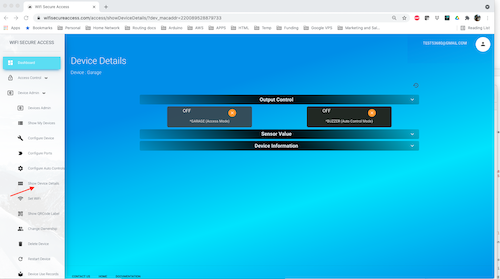
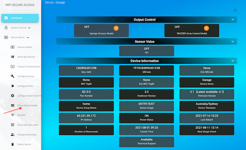
Now on this page, click on any device. It will show the details of that device. You will see its two output ports (GARAGE and BUZZER). It will show whether the output ports are currently Open or Closed, ON or OFF. If it is Open or ON, you will see a green circle with a check mark. If it is Closed or OFF, you will see an orange circle with a cross mark. You can click on the orange button of BUZZER. You will hear the buzzer sounding. Click this button again to put that off. If you click on the orange button on GARAGE, you will get an error message saying that this cannot be activated from this page, as this port is in Access mode.
Fig 10: Device Details.
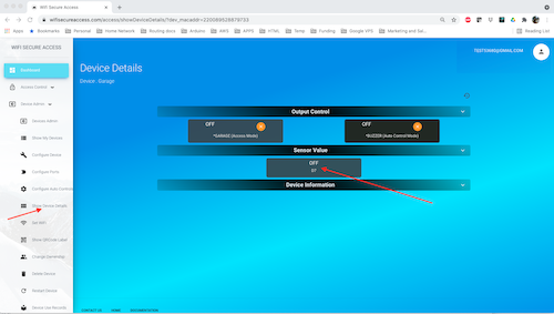
Now, click on Sensor Value on this page. You will see one sensor listed here: D7. The garage door controller has only one sensor input cabled to D7 of the microcontroller.
You will also see the current values sensed by these inputs. D7 is an ON/OFF type input. If you have connected a magnetic sensor connected to D7 as explained in section 2 above, and if you bring the two parts of the magnetic sensor close to each other, and if you refresh this page, you will see that this displays as ON. If you are not seeing this field as ON when the two parts of the magnetic sensor are close to each other, make sure that the gap between the two parts of the sensor is less than 10mm. Also make sure that the cable from the sensor to the device is not broken. Keep in mind that you have to refresh this page to see the new value if the sensor status changes.
Fig 11: Device Details.
Now, click on Device information. You will see a page similar to the following.
Fig 12: Device Details.
On this page (Fig 12), It will display all the details of this device such as its mac address, QRCode, NFC TagID, name of the device, firmware version, and so on. These are all for information. You may have a close look at all of them. Number of reconnects in this is the number of times the device lost connection to the server. If you see a higher number here, that indicates a weak wifi, or some frequent issues in connecting to internet.
On the firmware version tab, it will show you the current version and the latest version available. If the firmware is not up to date, you will see an orange button to click on to update its firmware.
3.7.1: Checking and Updating Device Firmware
To check the current firmware and to update its firmware, you can revisit this page (Fig 12) by clicking Device Details under Device Admin. Then click on Device Information to see the full information of the device. The Firmware version tab on this page will show the current version of the firmware on your device as well as the latest available. If the latest version or latest build is higher than the current build and current version, you will see an orange button on that tab. Click on that button to update its firmware.
We Strongly recommend updating the firmware to the latest by clicking the link on this page, if it shows new firmware is available
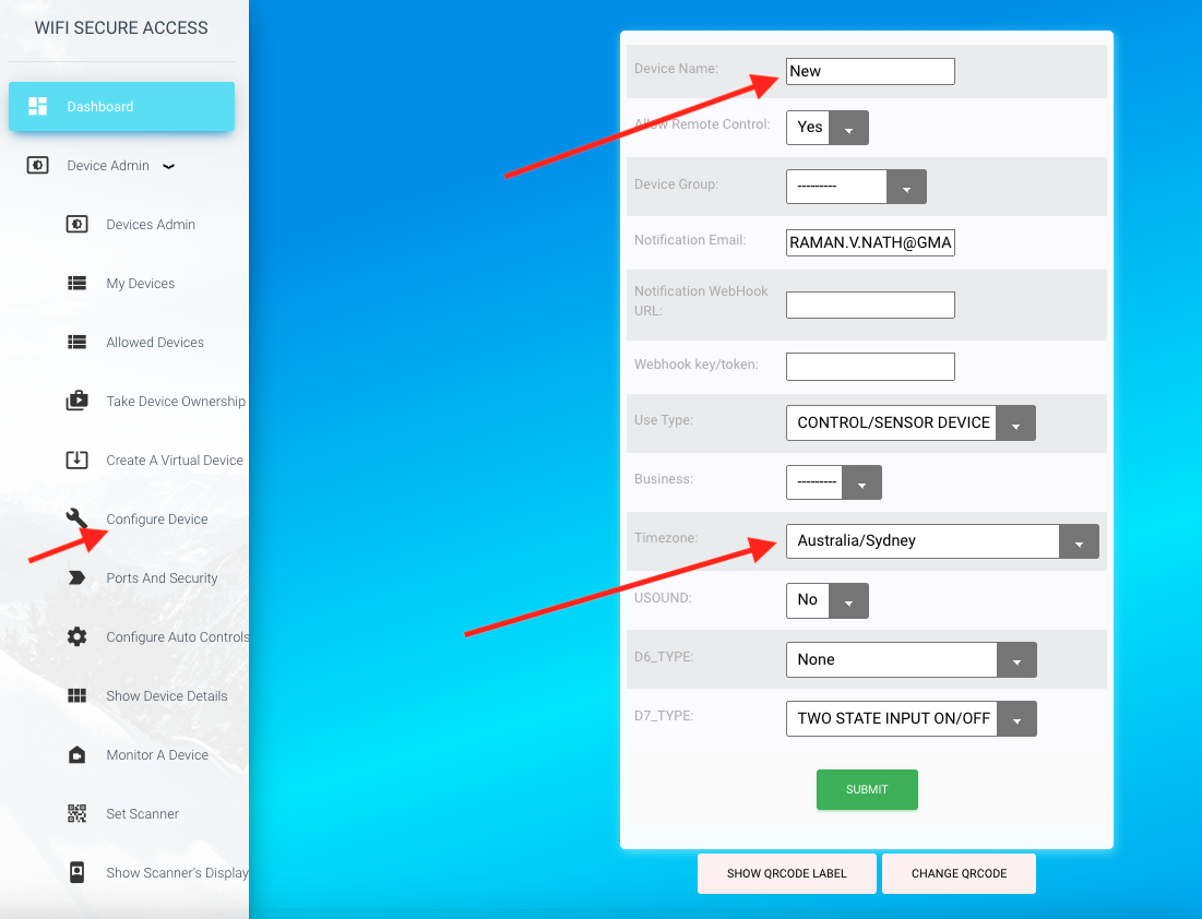
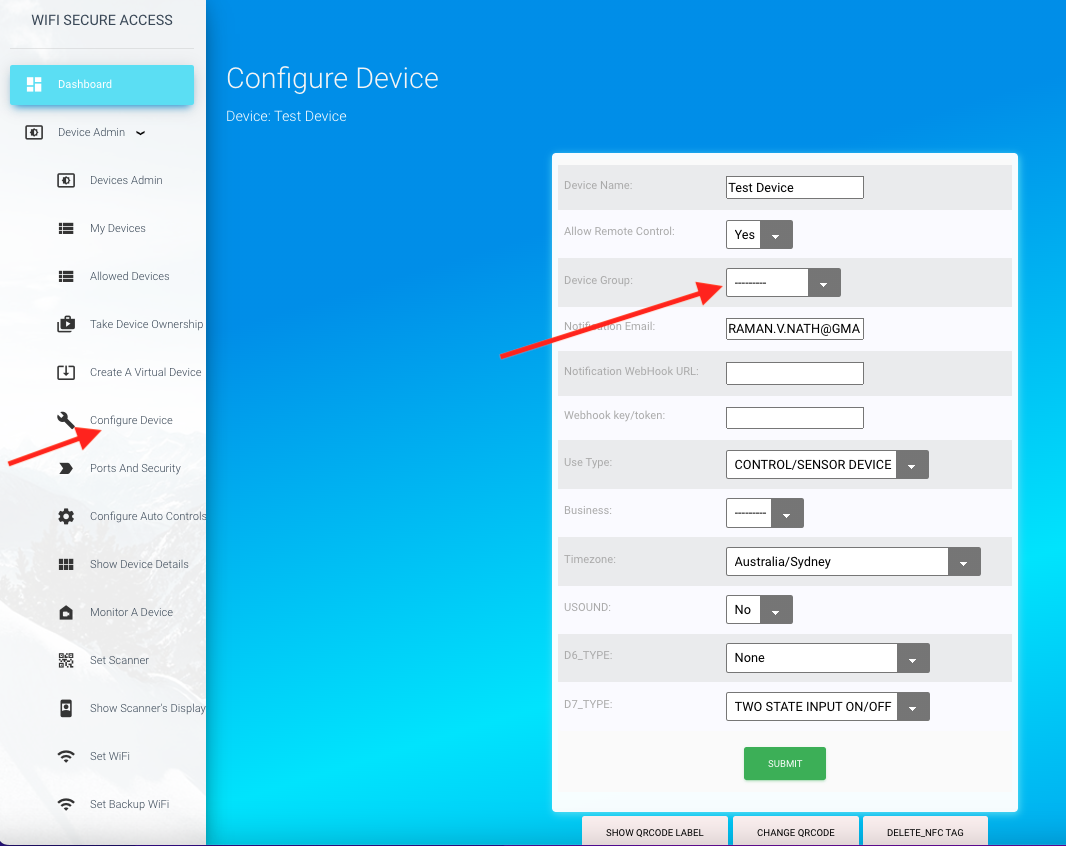
3.7.2: Changing the name of the device
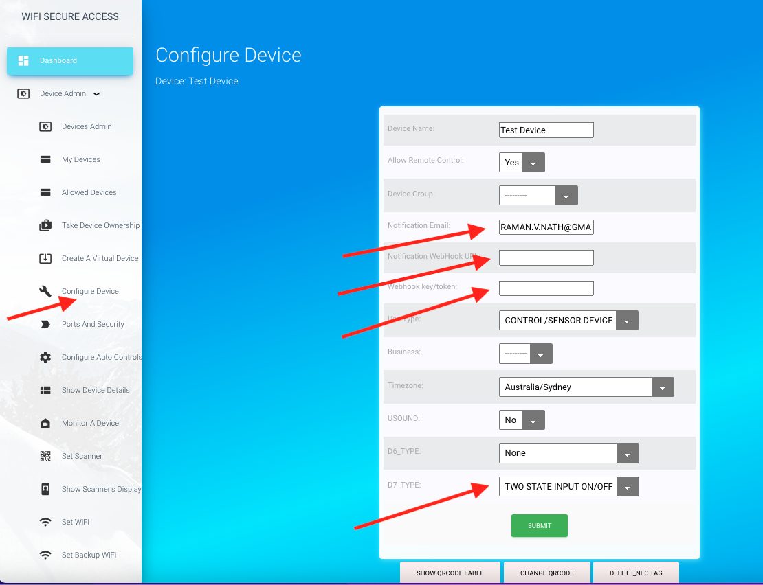
You can change the name of the device as well as the labels of each port, if you prefer. To change the name of the device, click on 'Configure Device' under Device Admin on the left side bar menu. It will present
a form similar to Fig 13. You can Change the name of the device to anything you like.
There are several other configurable fields on this page that may be left as defaults now. Check the Timezone on this field. By default, it is set to the timezone of the owner of the device. If this is not correct, you may change it to the timezone where this device is installed.
This helps in displaying all information in that timezone.
Click here to know the format of different time zones.
If this field is left empty, it will change it automatically either to the timezone of the owner of the device or UTC.
Fig 13: Configure Device.
3.7.3: Changing the name of the output port
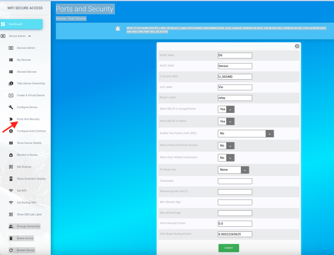
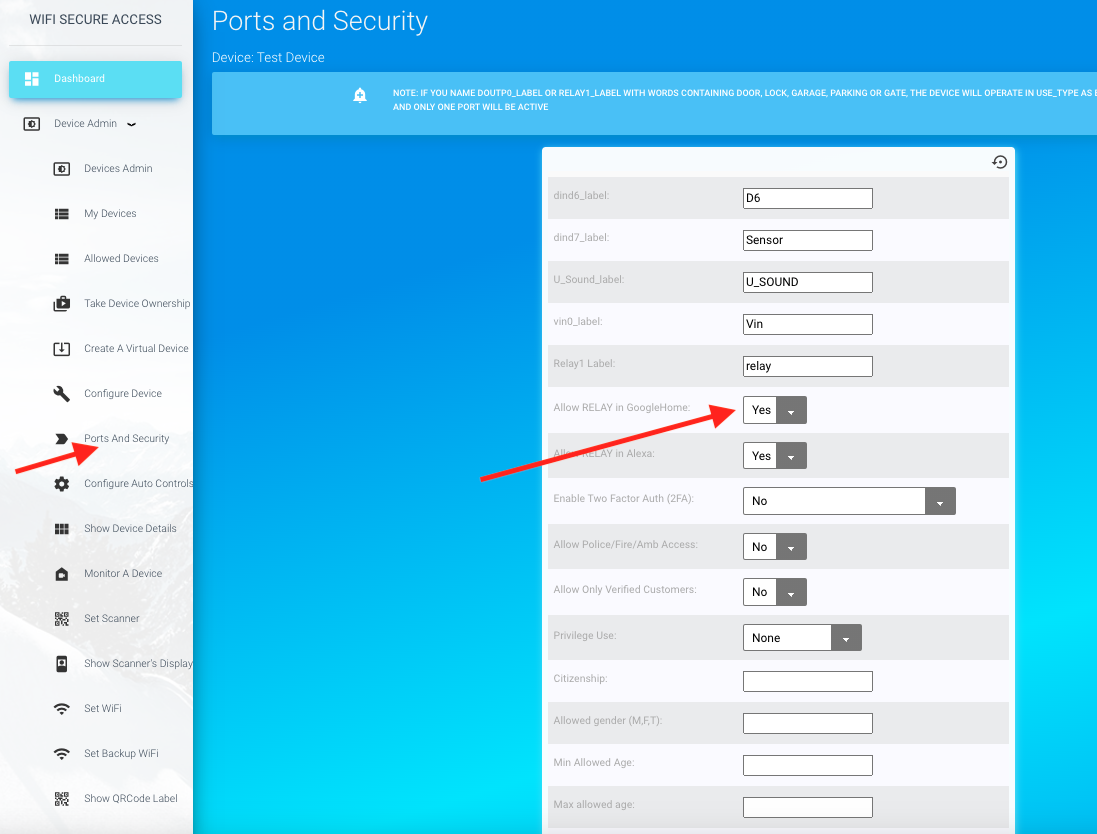
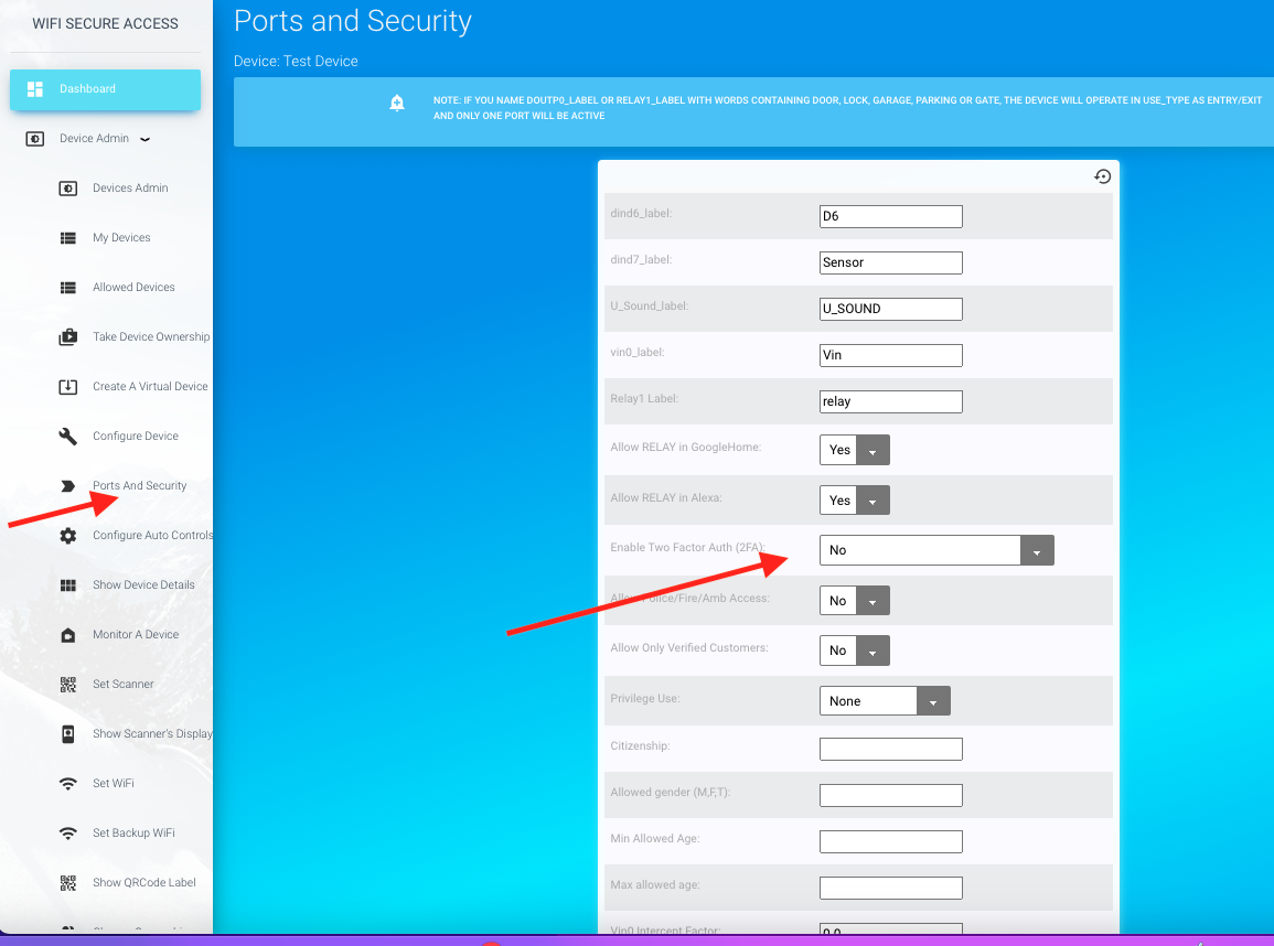
The names of the ports are also changeable by clicking on 'Ports and Security' under 'Device Admin' in the Dashboard menu. Fig 14 is the page that will show up when clicking 'Ports and Security". What you see here are the default values. Keep them as they are. If you change the Relay1_label to anything else without the word garage, it will add that 'garage' into that name.
On this page, you will see several other fields. The name of the dind7_label is D7. This is the label of the port to which the magnetic sensor is cabled to. You can change its name to anything that you prefer, or leave it as it is.
The fields Allow in GoogleHome and allow in Alexa are by default 'Yes'. That makes this garage door discoverable in GoogleHome and alexa. If you do not want this garage to be discovered in GoogleHome or alexa, you may set these to 'No'. The field 'Enable Two Factor Auth (2FA)' is a field for additional 2-factor authentication. If you set this to 'Yes', it will prompt for your personal pin whenever you try to open or close this garage. Your pin for this can be seen under My Profile. you can change the pin to anything you like.
Note: We recommend not changing these labels now.
Fig 14: Device Labels.
3.7.4: Activating a device
Once the device is installed and the names of the device and ports are configured, you can open/close the door/gate in one of several ways: 1) From the dashboard (Using a browser on computer or smartphone), 2) by scanning the QRCode or NFC tag of the device, 3) Using Google Home assistant on your smart phone, 4) Using Amazon Alexa, or 5) Making an HTTPS POST call from any of your other applications or programs. In the following sections of this document (sections 3.8 through 3.12), you will learn how to use all these different methods.
3.7.5: Disabling Remote Control
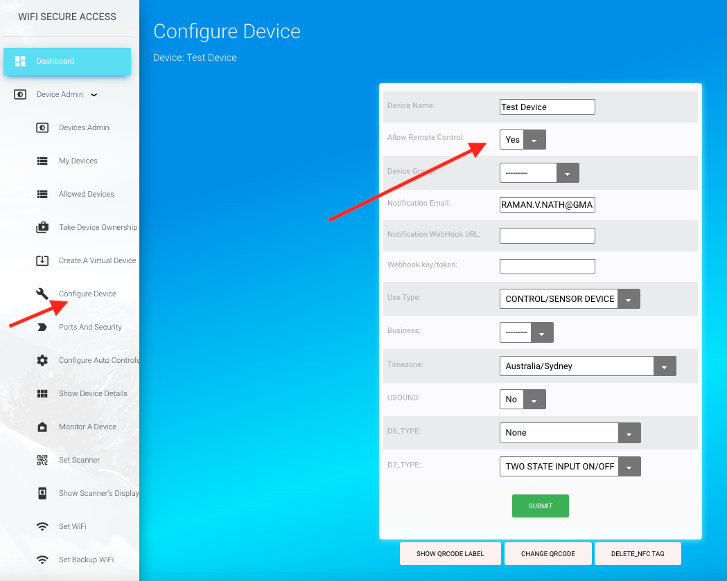
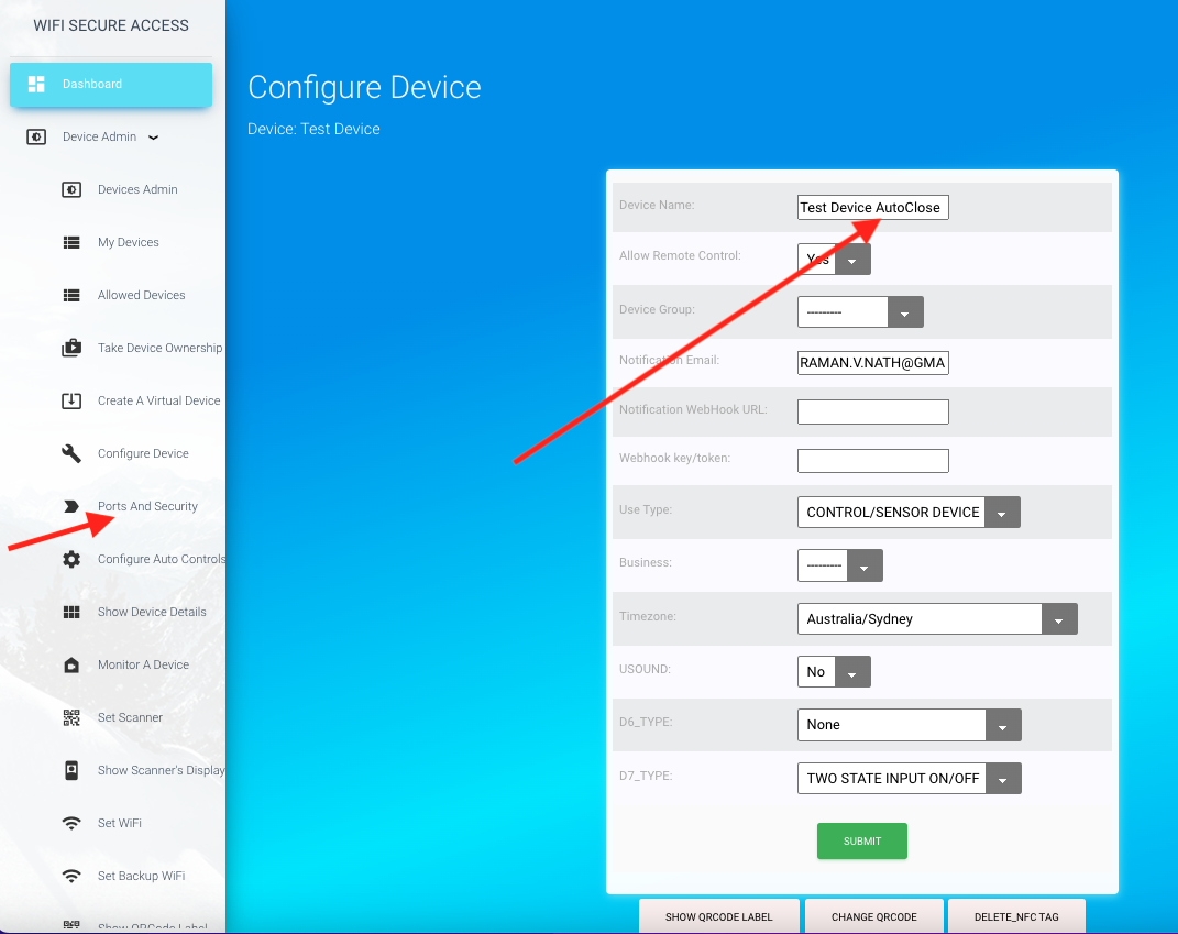
As said before, there are multiple ways to operate a garage door / gate. Some of those methods enable you to activate it from remote. For example, if you use Google Home or Alexa, or if you use "Activate a Device" button either from the App or from a browser, you are activating it from remote. In other words, you do not have to be at the garage door/gate to activate it (open or close). We call this as "Remote Control" of the garage door/gate. On the other hand, if you scan the QRCode or NFC tag of the device installed at the garage door/gate, you are activating it by being present at the garage door/gate. By default, every device is enabled to be activated from remote. However, if you do not want the garage door/gate to be activated from remote, you can disable remote control on the device. To do so, click on "Configure Device" under Device Admin in the Dashboard menu. On the page that opens, you will see a field "Allow Remote Control".
Fig 14_0: Configure Remote Control
By default, the field "Allow Remote Control" is set to 'Y'. That means that this device can be operated by any of the several methods listed above. However, if you set this to 'N', the device can no longer be operated from remote. This garage door/gate will be disabled in Google Home and Alexa. You also will not see a button for it in the 'Activate a Device' page. The only way, then, to operate this device is to scan its QRCode or NFC tag installed at the garage door/gate. That can be done only by being present at the garage door/gate and not from remote. This setting affects only the allowed users. It does not apply to the owner of the device. Owner of the device can operate it from remote regardless of this setting. Setting this to 'N', gives additional security that the allowed users have to be at the garage door/gate to open or close it.
3.8 Opening/Closing garage door/gate from the dashboard
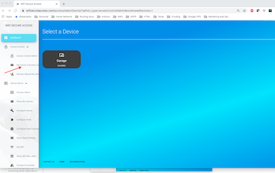
You can activate a device from the dashboard either using a browser on a computer or smartphone or through the WiFisecureAccess App on the smartphone. If you want to use a browser, go to the url https://wifisecureaccess.com. Then click on the dashboard tab on the top navigation bar. That will take you to the main index page. On that page, you will see a menu 'Activate a Device'. Click on that. That will show all devices that you are allowed to activate (similar to Fig 9). Clock on the name of the device that you want to activate. That will open that door/gate and display a success message (or Failure message) on a popup window.
You can also get to the dashboard through the WiFiSecureaccess App. Open the app on your smartphone. Then click on the 'Admin Dashboard' on the main scanner page of the app (Fig 14_1). That will take you to the main index page. There, you will see a tab "Activate a Device'. You can also see this 'activate a Device' tab in the dashboard menu, if you click ob the three lines at the yop right. To activate a device, click on 'Activate a Device' menu. that will display all the devices that you are allowed to activate (similar to Fig 9). Click on the device that you want to activate. That will open or close that door/gate.
You can also do the same thing by clicking the 'Activate a Device' in the main scanning page (Fig 14_1) of the WifiSecureAccess app. If you press that button, it will display all the devices that you are allowed to activate (similar to Fig 9). Then press on the device that you want to open or close. That will open or close that device.
Note: If the device is a gate or garage, they are, by default, in NoAutoClose mode. So, whenever you activate using this method, you are toggling the state of the garage/gate. If it is currently Closed, clicking the name of the device will open it, and, if it is currently Open, clicking will close it.
Fig 14_1: Open/Close Garage door
Note: As mentioned earlier in this documentation, everything that can be done by the wifisecureaccess app on a smartphone can also be done using a browser on a computer, except scanning QRCodes and NFC tags.
3.9 Opening/Closing garage door/gate by scanning either QRCode or NFC tag of the Device
As you know by now, by default, each device has been assigned a unique QRCode, and is pasted on the box of the device. You can also view and print its QRCode at any time by pressing Device Admin → Show QRCode Label in the dashboard menu. You can also change the QRCode of any of your devices in the 'Configure Device' menu (Fig 13).
To activate garage door using QRCode, you can scan this device using wifisecureaccess app. Open the app, go to the scanning page and press Scan QRCode. The camera will become active, and now scan this QRCode. That will activate that device. If it is currently Closed, it will open it, and if it is currently Open, it will close it.
It is also possible to assign a unique NFC tag to a device.
If you find a need to use NFC tags instead of QR codes, you can do so by purchasing NFC tags and associating it with the device. We support only Mifare Ultralight 14443-3A type of tags which has 7 bytes of UID. These are very inexpensive tags that you can buy from anywhere. These tags come as stickers as well. Given below is an example link to buy from Amazon. This is just an example. If this link is not available, or if you would like to use a different type, search for a similar item in ebay or Amazon. These NFC tags are available in different type of shapes and packaging. You can use the type you like so long as it is Mifare Ultralite with 7 bytes of UID.
To associate an NFC Tag with your smart device, open the app, go to the scanning page and press 'Scan NFC Tag' and scan the tag that you purchased.
If this is a new tag and if it is not associated with any other device within our system, you will be taken to a page prompting you to select one of your devices to associate this tag to. The pulldown list will contain all the devices you own (all those devices that are powered on). iIf you have only one device with garage door, you will see only that in the pulldown menu. The Exit Tag option on this page may be left aas 'N'. Once you select a device and press submit, it will associate this tag with that device. On the other hand, if you are scanning any tag that is not compatible, or is being used by some other device, you will receive an error message.
Once associated with your garage door, and if you scan it again, it will activate your garage door just like the same way you scan a QRCode.
You can fix the NFC Tag and/or the QRCode label at any convenient place to access this device.
Note: In our IOT system, QRCode as well as NFC Tags are both secure and both do the same job.
Even though anybody can scan these NFC tags or QR codes, only the owner of the device as well as those who are allowed by the owner can access/activate the device. For additional layer of security, you can also enable Two Factor Authentication(2FA) as explained in section 3.13 in this documentation. NFC tags are safer than QRCodes as NFC tags cannot be copied (we are using UID of the tag). And, if you do not want anybody to operate this device from remote, you can set "Allow remote Control" (Fig 13) to 'N'.
3.10 Using Google Home assistant to open or close your garage door/gate
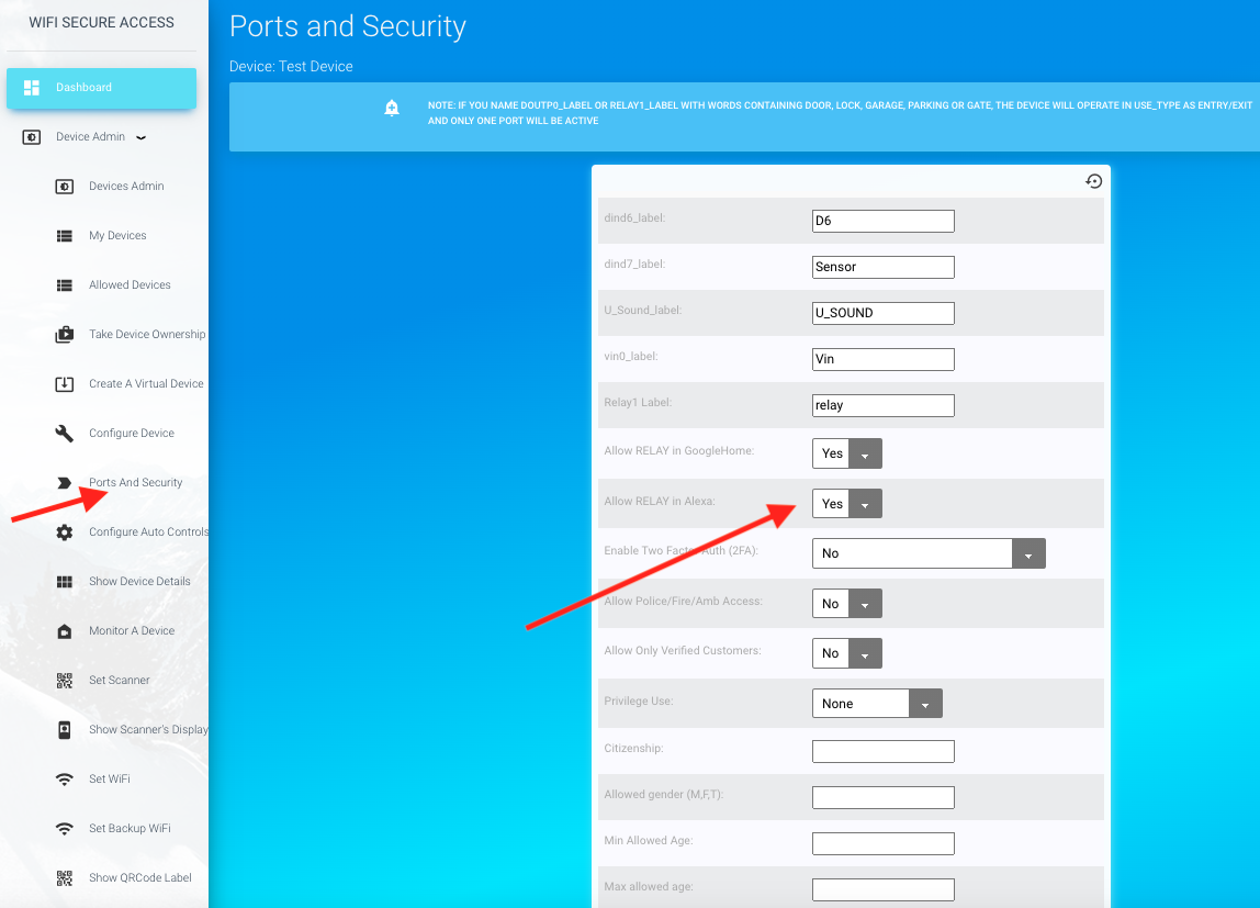
WiFisecureAccess devices are compatible with GoogleHome, and, therefore, you can use Google Home assistant to open/close your garage door. By default, the device is enabled to be discovered by GoogleHome. To check or to change, click on 'Ports and Security' under Device Admin in the dashboard. You will see a page similar to Fig 14A.
Fig 14A: Enabling Google Home assistant
On this page, make sure that 'Allow RELAY in GoogleHome' is set to 'Yes', if you want the garage to be activated using Google Home assistant. If you do not want to use Google Assistant to activate garage door, set them to 'No' and press Submit button.
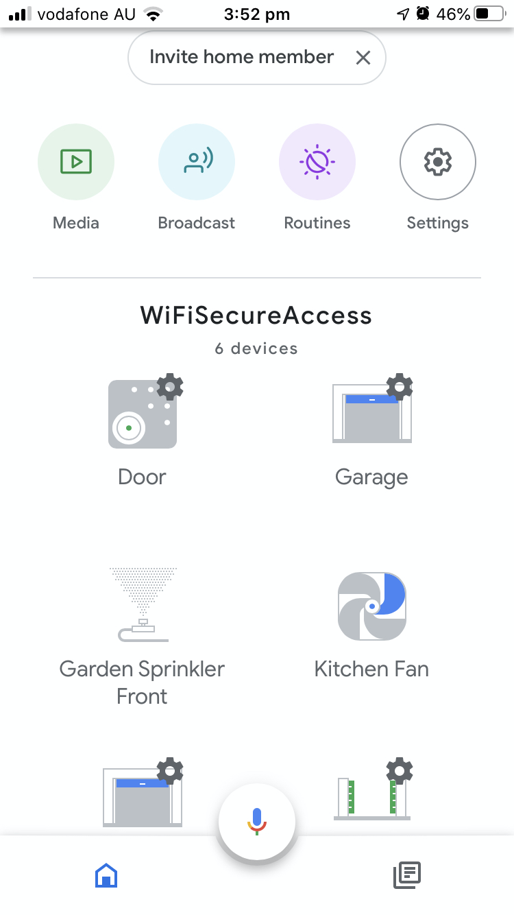
If this is enabled to be discovered by Google Assistant, you can discover these ports in Google Assistant. Press + button in Google Home to add devices. Then press 'Set up device'. Then press 'Have Something already set up". On that page in Google Home, search for WiFiSecureAccess and select it. That will discover all the allowed ports of all your allowed devices.
Fig 14B: Google Home Page
You can now rename these whatever you would like to. Hereafter, you can say 'Hey Google, open *name of the device*'. That will open that garage door. Note that you can change the name of these ports in the "Device Configuration" menu (Fig 13) in WiFiSecureAccess dashboard, and/or within the Google Home. The name in Google Home need not necessarily be the same as that in the configuration within the dashboard of wifisecureaccess.com.
Note:
It is assumed that garage doors and gates do not close by itself when opened. In order to close it, you have to give another voice command.
If you want the garage door or gate to auto close after opening, you can add the word "AutoClose" in the name of its port. AutoClose must be added in the name of the port and not the name of the device. These words are case insensitive. In fact, if you add the word "AutoClose" in the port label of garage, the smart device will close the garage door automatically by applying a pulse to the controller after the duration specified in the portcontrols of that port. Refer to Section 3.15 of this documentation for more about configuring AutoClose. If garage is in AutoClose mode, you can make it stay open if you say "Hey google, Open garage" after it has come to an open position and before it gets auto-closed.
To know the current position of the door or garage door or gate exactly from remote, you need to install a sensor and cable that to the smart device as explained in section 3.14 of this documentation.
3.11 Using Amazon alexa to open or close your garage door/gate
Garage doors and gates can also be activated using Amazon Alexa. You may download and install Amazon Alexa on your smart Phone. In Alexa, press 'more' and then click on 'skills and games'. Now search for wifisecureaccess, then enable that skill. When enabling the skill, it will take you to Wifisecureaccess.com and will prompt you to enter your email and password. This is your password for wifisecureaccess.com. If the entered credentials are correct, you may press Discover Devices. That will discover all the wifisecureaccess devices that you own.
As said earlier, garage is allowed to be discovered by Alexa by default. However, if you do not want this to be discovered by alexa, you may change the configuration. To check and change this configuration, click on Ports and Security under Device Admin the dashboard menu. You should now see a page similar to Fig 14C.
Fig 14C: Enabling Ports to be discovered by alexa
On this page, select 'Yes' for "Allow RELAY in Alexa" if you want garage to be discovered by Alexa. Press Submit after making the selection(s). Then, login to Alexa on your smartphone and discover ports as you did before. If all settings are correct, you should be seeing these devices discovered in your Alexa application on your smart phone. You can now open the door/gate by saying, for example, "Alexa, open XYZ", where XYZ is the name you have given to the garage or gate. Similarly, to close the garage door or gate, you can say "Alexa, close XYZ". All the features of Alexa are now available to you for managing the equipments connected to this smart devices.
3.12 Opening/Closing garage/gate with an HTTPS POST call
You can also open or close the garage/gate from any of your other application programs using an HTTPS POST call. This helps integrate the WiFiSecureAccess system/devices with your other application programs. This feature also helps the developers to integrate this with their programs.
To open or close the garage door, make an HTTPS POST call with the following details:
POST HTTP/1.1
Host: wifisecureaccess.com/devicePortsJson/
Content-Type: application/json
data = {
"email": email,
"password": password,
"device_name": device_name,
"action": action,
}
--where email is the email address of the owner of the device, password is the password of the owner of the device, device_name is the name of the device and action is either 'ON' or 'OFF'.
Refer to Section 6.0 of this documentation below to see more details about this and to see a sample python program.
PS: If you plan to use this type integration with any commercial applications where usage rate is high, please Contact Us prior to doing so to avoid interruption and to get support
3.13 Enabling Two Factor Authentication (2FA) on opening door/gate
By default, the doors and gates are secure, meaning that nobody else other than those who are allowed will be able to open/close them. But, if you are interested in an additional layer of security, you can enable 2FA (two fact authentication) on these controllers. If you enable it, the user will be prompted for two factor authentication when trying to open that gate or garage door. To enable 2FA on any device, click 'Ports and Security' under Devices admin in the dashboard, just like the way it was done when enabling GoogleHome. You will see a page as in Fig 14D.
Fig 14D: Enabling 2FA on Ports
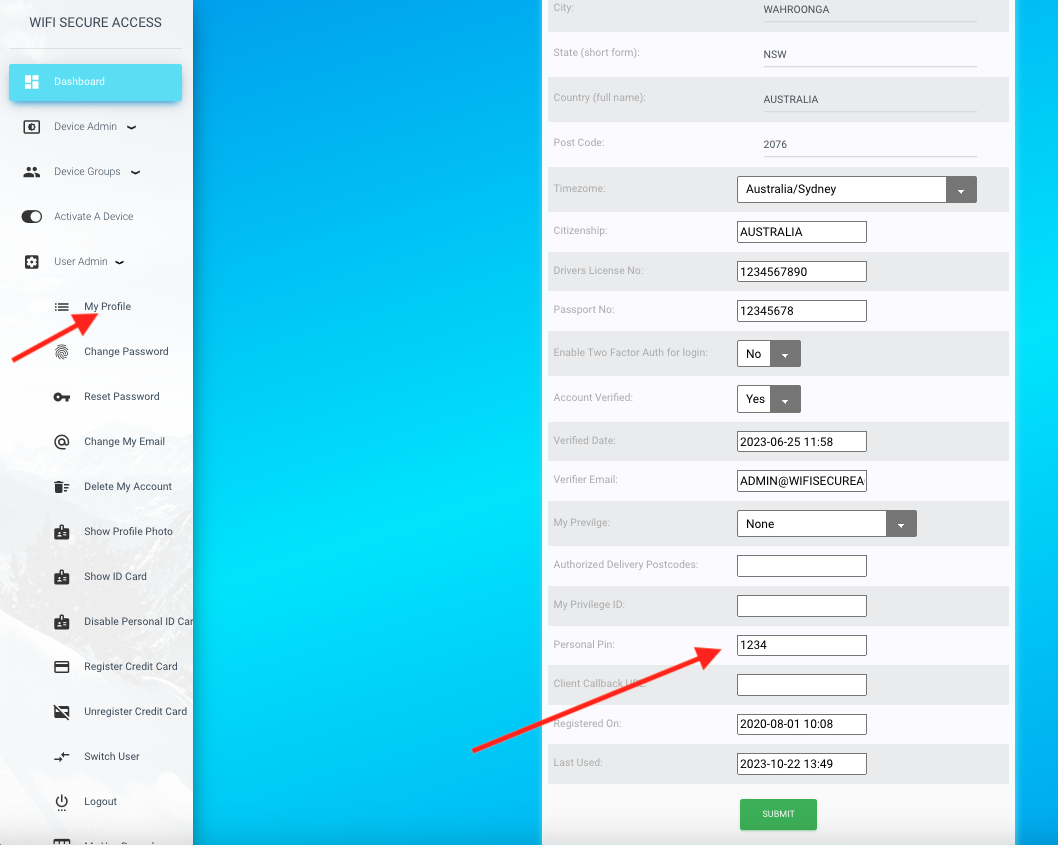
On that page, you will see a field 'Enable Two Factor Auth (2FA)'. By default, it is disabled. There are multiple optiions for two factor authentication. The options are Personal Pin, 'Send code by email', or 'face recognition'. You can choose any one of them, and press Submit. Google Home always uses Personal Pin, regardless whether you set anything other than 'No'. Once enabled, whenever you tell Google assistant to, activate that device (such as 'Hey google, Open Door'), Google Assistant will respond 'Can I have your pin?'. If you are activating this port by scanning QRCode or NFC tag or by pressing 'activate' button on your smartphone, the system will prompt for the pin before before activating that door/gate. You will have to enter your personal pin correctly to open the door. Your pin can be seen under your profile (click My Profile under User Admin in dashboard to see it). By default, the pin is 1234. You can change it to anything you like. This 2FA is an extra layer of security, and it is optional.
If you set 'Enable Two Factor Auth' to 'Send Verification Code' or 'Face Recognition', these will be used when trying to open this door/gate either by scanning its QRCode or NFC tag, or when pressing its button under 'Activate a Device' on a smart phone or computer. If you set it to 'Personal pin', it will prompt you to enter the personal pin. If you set that to 'Send Verification Code by Email', it will send a code to your email address. You will have to enter that code to open that door or gate. And, if you have set this to 'Face Recognition', it will open up your camera on your smartphone or computer and ask you to take a selfie. It will then match that photo with your profile picture to provide access.
Fig 14D1: My Profile
Note: The above method of 2FA will not work with Alexa. For 2FA in Alexa, you need to set it in Alexa itself. Refer to documentation on Alexa for setting pin codes for Locks and Doors.
3.14 Enabling Sensor and Enabling Notifications
As mentioned earlier, installing and enabling sensor is optional. However, without the sensor enabled, the current position of the garage door (open or closed) that you see in the app or a browser may not be correct. If you also operate the garage door either manually or by any other remote control, WiFiSecureAccess system will not know about it unless the sensor is enabled. So, in the absence of the sensor, what you see as the current position (open or closed) on the app or browser may not be correct.
Also, in order to send notifications, or to sound buzzer when the garage door/gate stays open for a long time, you need to install the magnetic sensor on the garage door and cable it to the smart controller as explained earlier in section 2.2 of this documentation. Check if the sensor is working before enabling notifications. You can see whether the sensor is currently ON or OFF by clicking 'Device Details' under Device Admin in the dashboard menu (refer Fig 11). Check if it reads ON when the door is closed and OFF when door is open (or, vice versa depending on how you installed the sensor). If it is not working, check if the gap between the two parts of the sensor is within 10mm when they come close (closed position of the door/gate). Also, check the cable and connections.
If you have installed sensor, check and make sure that D7_type in the configuration is selected as "TWO STATE ON/OFF". To do that, click on "Configure Device" under Device Admin in the dashboard menu. That will open a page as shown below.
Fig 14E: Configure Notifications
On this page, you should be seeing D7_type as TWO STATE ON/OFF. If not, select it as TWO STATE ON/OFF and press submit.
On this same configuration page (Fig 14E), you can set the fields for sending notifications. Notification Email field shows the email address to send email notifications. By default, this is set to the email address of the owner of this device. You can change it to any other email address, if you want. If this email field is left blank, no emails will be sent.
The fields Notification Webhook URL is the URL of your webhook to which a call will be made when conditions are met to send notifications. Webhook key/token is the key or the token of your webhook. You may enter those in these two fields, if you are interested in making such calls to send notifications. If the Webhook URL is left blank, it will not make any such calls to webhook URL. The call is an HTTP POST call with the key token in the header ('Authorization': webhook_key), and with some data in the body in JSON format. The data will have the device name, sensor_name, current value of the sensor, and a message. The following is the type of call that will be made:
Next, the notifications have to be enabled such that it sends notifications when the garage door stays open for a long time. It is also possible to configure it to sound an alarm (buzzer) either once or repetaedly when the garage stays open.
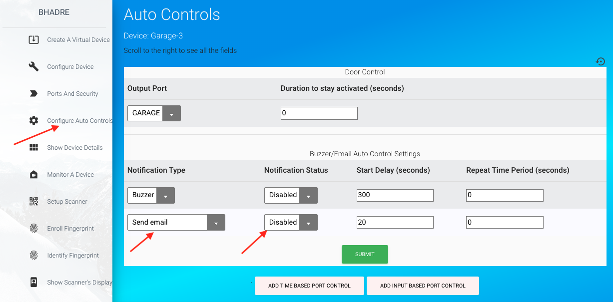
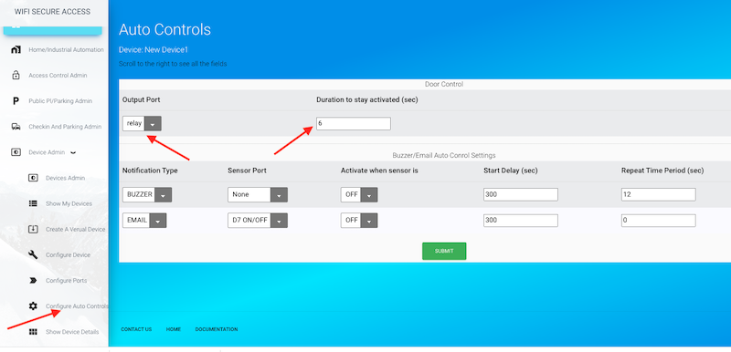
To enable notifications, click on Configure Auto Controls under Device Admin in the dashboard menu. That will show you a page similar to the following.
Fig 14F: Enabling Notifications
In this page, the first row may be ignored unless you want to set AutoClose. So, the field "Duration to stay active' in the first row has no effect unless AutoClose is to be configured. More about that can be found in the next subsection of this document.
To send email notifications or to send a webhook call when the garage stays open, you need to set the next two rows on this page. The last row on this page is the setting for sending emails notification. To enable email notification, click on 'Sensor Port' in the last row of this page and select 'D7 ON/OFF'. Then set the delay time. This is the time it will wait to send notifications or to sound buzzer since the garage was opened. If you want the notifications to be sent periodically when garage stays open, you can also set the 'Repeat Time Period' in seconds.
Similarly, if you want the buzzer to sound, you can select 'Sensor Port' as 'D7 ON/OFF' for the row corresponding to BUZZER (last but one row in Fig 14F). Here also, you can set the delay time and time period of the alarm as you desire. Note that, normally the defaults will work.
Selecting 'Sensor Port' as 'None' will disable that notification. That will also disable reading the sensor, and the current status of the door that it reports may not be correct.
Note: It is important to enable any one of the notifications (either sounding buzzer or sending email) for knowing the current position of the garage door/gate accurately from remote. This is because the sensor is read only if any one of the notifications is enabled.
Special Note: On this page of Auto Controls (Fig 14F), you can see a field "Activate when sensor is". This is by default "OFF". Do not change this if the sensor is installed as described earlier with two of its parts (A and B) aligning themselves (they come next to each other) when the garage/gate is fully closed. In fact, that is the best installation for a garage door/gate. However, there is a less desirable option of installing the two parts of the sensor such that they align themselves when the garage/gate is fully open. If you install the sensor that way, this field "Activate when sensor is" has to be set to "ON". We are not recommending this installation because it may report that the garage/gate is closed when it is half open.
3.15 Configuring Auto Close
By default, garage door will not close by itself after opening. So, you will have to manually close it any time after opening it. With WiFisecureAccess smart controller, it is also possible to configure auto-closing of the garage door. For example, say, you want the garage door automatically closed 2 minutes after it is opened. This can be done by adding a word AutoClose in the port label of the port of the smart device connected to garage door controller. To configure this, click on 'Configure ports' under Device Admin in the dashboard menu. Then change the name of the relay1 Label from 'GARAGE' to 'GARAGE AutoClose'. Then press submit.
Note: the word AutoClose is a single word, case insensitive.
Fig 14G: Setting AutoClose
Next, you need to set the duration for which the garage door should remain open before closing it automatically. Click on Configure Auto Controls under Device admin in the dashboard menu. Then in the first row, change the value of 'Duration to stay activated (sec)' to whatever you prefer. If you want the garage door to remain open for 2 minutes before closing, then set this to 120. Press submit.
Note: This first row of control on this page has no effect if AutoClose is not set. The field 'Duration to stay active' is used only if AutoClose is set. So, if AutoClose is not set, The value in this field can be anything other than 0.
Fig 14H: Setting AutoClose Duration
Note: The duration is the time since you press the button to open the garage and not the time since the garage door comes to a full open position. So, make sure not to set this duration lower than the time needed for the garage/date to come to a full open position.
With the above configuration with AutoClose, the garage will automatically get closed two minutes after it is opened. With this autoClose in place, suppose that you want to keep the garage remain open anytime after you open it, you can use either Google Home or alexa, and say 'Hey google, Open *name of the device* during the time the garage is open. So, if you try to do so during the period when the garage is open (when in autoclose mode), it will cancel autoclose and will stay open. You can also do this by activating the device using the app when the door/gate is in open position. Then, if you want to close the garage, you can say "Hey Google, Close *name of the device*". Or, alternatively, activate the device using the app. This is a special handy feature of our smart device that you can configure and use.
PS. Make sure that the firmware of the device is 4.5 or above to get all the latest features of AutoClose. Update firmware if current firmware is less than 4.5
PS. It is assumed that the cabling of the smart device is to the push button terminal of the garage door controller.
Therefore, the smart device applies a pulse to it for opening or closing. If you are using it for opening a gate where
it needs anything other than a pulse, this AutoClose feature will not work. Please Contact Us for any help
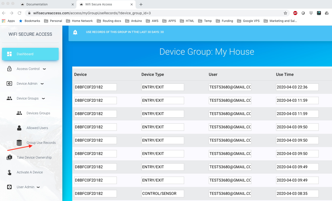
3.16 Device Use Records
The system keeps record of the use of this garage door for 30 days. At any time, you can see who used this garage door and at what time. To see the use records, click on 'Device Use records' under 'Device admin' in the dashboard menu. You will see a page similar to the one in Fig 38E with two columns (User and use_time).
You can download these use records to your computer, if you want to do so for keeping any records, or for analysing the data. To download, click on 'Download Device Use records' under Device Admin in the dashboard menu. There you can provide the dates between which you want to download the data. Leaving any of these dates will take that date as open-ended. Leaving both dates as blank will download all the available use records for the past 30 days.
You can also add a program in any of your applications to download these records, and do analysis. These use records can be read using a python program. Refer to section 7.1 of this documentation.
4.0 Allowing Multiple Users
This section explains how multiple users can be allowed to use a device. The owner is allowed to use all his devices all the time regardless of the settings described in this section. This section explains how the owner can allow others to use his devices and how to control and manage their authorization.
4.1 Allowing Others to Use Your Devices
You can allow or authorize the others to use your smart device. To allow someone else to use your device, they have to be registered with wifisecureaccess.com. So, request the other user to register with wifisucureaccess.com. To register, either download the app and open the app and press Admin Dashboard, or go to https://wifisecureaccess.com and click on dashboard in the top navigation bar. When it requests you to login, click on 'Create a New account'
Once they are registered, you add their email address to the Allowed Users group of your device as per the steps below:
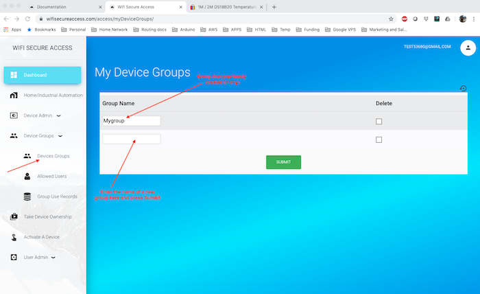
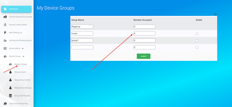
First create a Device Group. This can be done by clicking 'Devices groups' under 'Device Groups' in the Dashboard menu.
Fig 36: Configure Device group
This page will display all the device groups that you have created so far. To add a new device group, just enter the name of the group in the bottom empty row and press submit. Make sure that the name that you entered is a new name. You can create as many groups as you need.
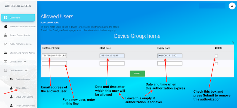
Next, click on 'Allowed Users' under Device Groups in the Dashboard menu. If you have created multiple groups, you may be prompted to select a group. You will then see a page similar to the one shown in Fig 37.
Fig 37: Configuring Allowed Users of a Group
In this form, enter the email address of the one whom you want to allow to use your device, and press Submit. If you have several users whom you want to allow, enter the email addresses of all of them, one at a time. You have now created a group of users.
PS. If you want to allow everyone, you can enter an email address *@gmail.com. If this email address is in any device group, everyone can activate that device to which this group is associated by scanning either its QRCode, or NFC Tag, but not by using voice prompt through Google Home or Alexa. This wild card email address will not work when this group is associated with a device in parking lots or public places.
Note: When you added the email address of a user in a group, you could add a start date and an expiry date as well, if you want. Start date is the date and time this user will be allowed. He will not be allowed before that date and time. Once an expiry date is added, that user will not be allowed after that expiry date. The format of these dates is yyyy-mm-dd hh:mm. Leave these date blank if the user is allowed all the time with no start date and no expiry date.
You can also remove any user from this group at any time by checking the delete box against that user's name and pressing Submit.
PS: In the latest version, you may find an additional column named "Permissions" in the above form. Leave that blank. That is a field used for special purposes when we install this ourselves for large installations.
Next, you need to associate this group to your device so that all users in this group are allowed to use a device. To do that, click on 'Configure Device' under Device Admin in the Dashboard menu.
Fig 38: Configuring Devices with Device Group
In this page, select your device group, and press Submit. If all the above configurations are successful, all users in the selected device group are allowed to use this device.
When someone is allowed to use to use your device, they will see this device in the list of devices they can use. Also, when they click on 'Show Device details', this allowed device will show up. If this device's port is enabled for GoogleHome or Alexa, the allowed users will show this device in GoogleHome or Alexa when they discover wifisecureaccess devices. But, keep in mind that the allowed users cannot change the configuration of a device.
So, if you install this device at an access door to open or close a door, all allowed users will be able to open and close that door. If you have set a start date, that user will not be able to open the door before that date. If you have set an expiry date, they will not be able to open or close this door after that expiry date. In later sections of this documentation, you will learn how to install this device as an access controller of a door.
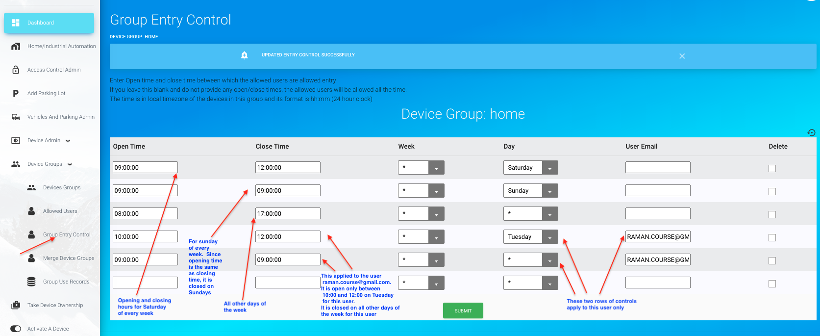
4.2 Configuring Group Entry Controls
It is possible to create entry controls on the members of a device group. For example, if you want to allow the members of a group only between some specific time of a day, you can set the opening and closing times for a group. To do that, click on 'Group entry Control' under Device Groups. This tab will be available only if you have created a group. If you have created multiple groups, you will be prompted to select a group. Once selected, you will see a page similar to Fig 38A.
Fig 38A: Configuring Group Entry Control
On this page, set Opening time and closing time for this group. In the field 'Week' and 'Day', you have multiple options. If you set * for week, it applies this opening and closing times for all weeks of the year. Or, you can select a week that you want this applied to. Week is the Gregarian week number. If you do not know the week number corresponding to any date, just enter the date in the YYY-MM-DD format. It will find its corresponding week number. If you enter a week number, this rule applies to that week only. Similarly, if you select * for Day, it will apply this to all days of a week. If you want this to apply to a particular day only, then select that day. You can also select the email address of a user this control must apply to. Then press submit.
Note: The general rule is that a member of the group is always allowed unless there is an open/close time in this table showing that the group is closed for him/her at that time of the day, on that day of the week of that year. An entry with opening time the same as closing time will mean no entry on that day of that week.
If no rows of controls is present, all users of this group will be allowed all the time, meaning that it is open all day, every week of the year. You can create a special closing and opening hours for a particular user by adding his email address in the 'User Email' field. If no user email is given, that opening and closing hours are applicable to everyone in that group. If opening and closing hours are missing for a user for any day of the week, the rule applicable to all will be used for that user.
You can add as many rows for each user as you want so long as those controls are different from each other. In other words, you can create an opening and closing hours for a user on Monday, another one for Tuesday and another one for, say, Thursday. And, if you leave all other days without specifying any control for that user, the general opening and closing hours used for all members of the group will be applied to this user.
You can also create multiple opening and closing hours within a day
Shown in Fig 38A is an example. In that, the first row is the opening and closing times for everybody on Saturday. The second row is the opening and closing times for everybody on Sunday. And, as the opening and closing time are the same on Sunday, it is effectively closed on Sunday. The third row is the opening and closing time for everyone on all other days of the week. The fourth and fifth rows apply to the user whose email address is given in the 'User Email' field. As per the fourth row, this user will be allowed between 10:00 and 12:00 on Tuesday, even though, all the others are allowed between 8:00 and 17:00 on Tuesdays(as per the third row). And, again, the fifth row specifically says that this user will not be allowed on any other days of the week. So, as special opening and closing times are given for a particular user covering every day of every week of the year, that rule will be applied to that user, and not the general rule. However, if a rule is not specified for a user for any day, the general rule will be applied to him for those days.
If there are no rows present, or if there is only one row with * for week and * for day, with user email empty, that means that it is open all days of the week and all weeks of the year for all the users in that group. In addition to this, you can create special opening/closing hours for each and everyone in the group. They can be either the same or different for each user.
If you do not want to anyone to enter, create a control with opening and closing hours the same. If you want to allow anyone, say, between 10:00 and 12:00 on Wednesday and do not want to grant any access on any other day, create two rows of control. In the first row of control, set opening time as 10:00 and closing as 12:00, week as * and day as Wednesday. In the second row of control, enter any time (say, 10:00) for both opening and closing time and select * for week and * for day. And, if you leave the user_email blank, these two rules will be applied to all those in the group for whom no other special rules are created.
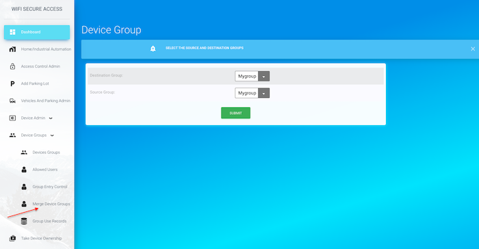
4.3 Creating a New Group by merging members of two other groups
If you have created two groups and you have added members in each group, and if you are interested in creating ai new group that should contain members of both the other groups, you can do so. First create a new empty group by clicking 'Devices Groups' under 'Device Groups' in the dashboard menu. Then click on 'Merge Device Groups' under 'Device groups' in Dashboard menu. You will see a page similar to Fig 38B.
Fig 38B: Merge Device Groups
On this page, select Destination group as the new empty group that you just created. Then, select the first group that you want to add to this in the 'Source Group' field. Then press Submit. Next, repeat the same to add the second group to the same new group by clicking 'Merge Device Groups' and selecting Destination Group as the new group and selecting the second group for the 'Source Group' field. Then, press submit. Now, you have a new group with members of two of the other groups that you selected.
4.4 Entering an allowed user into a group using an HTTPS POST call from any of your applications
You can populate the allowed users of any group from any of your applications such as a booking platform using an HTTPS call. This feature helps integrate the WiFiSecureaccess door controller with your applications such as a booking platform. If these devices are installed, for example, on the door of a hotel room or an AirBnB room, the application platform that makes the booking can enter the customer's email and their start date and expiry date directly into the allowed user's list of the group associated with the controller device. If done, the customer will be allowed to open the door during the period between start-date and expiry-date. The customers can open the door either by a voice prompt, or by scanning the QRCode or NFC tag fixed on the door. Thus, this is an ideal system for hotels and AirBnB users. This eliminates the need to pass on the keys or access cards to the customer.
To add the user to the device's group, make an HTTPS POST call with the following details:
POST HTTP/1.1
Host: wifisecureaccess.com/loadAllowedUsersJson/
Content-Type: application/json
data = {
"email": your_email,
"password": your_password,
"device_group_name": device_group_name,
"customers": customers
}
-where customers is a double list of customer details.
customers = [customer1, customer2, customer3, ....]
-where each customer is a list as below:
[email_address, start_date, expiry_date]
For example, if you want to add two customers to the allowed group of a device, the customers should be as follows:
customer1 = [customer1_email, customer1_start_date, customer1_expiry_date]
customer2 = [customer2_email, customer2_start_date, customer2_expiry_date]
customers = [customer1, customer2]
Note: Leave start date and expiry date as "", if there is no start date or end date for that customer. If there is no start date, that means that the customer can access immediately. If there is no expiry date, the customer is authorized forever.
You can also remove any customer from the device's group with another HTTPS call as follows:
POST HTTP/1.1
Host: wifisecureaccess.com/removellowedUsersJson/
Content-Type: application/json
data = {
"email": your_email,
"password": your_password,
"device_group_name": device_group_name,
"customers": customers
}
-where customers is a list of email address of the customers that you want to remove from the allowed list.
customers = [customer1_email, customer2_email, ......].
Refer to Section 11.2 of this documentation below to see more details about this and to see a sample python program.
4.5 Uploading allowed users from a file on your computer
If you have a file with email addresses of all the allowed users, you can upload that directly to any of the device groups, if you want. The file must be a txt file with multiple lines, with each line for each customer. The format of each line must be as follows:
customer_email, start_date_time, expiry_date_time
Each line must have the first field as customer email address. The second and third fields are start date and time at which that customer will be allowed, and the expiry date and time when his access will be revoked. These two field are optional. You can leave either or both. These three fields are to be separated by comma (,). Customer email must be provided and cannot be omitted. The format of the start_date_time and expiry_date_time is yyyy-mm-dd hh:mm. Here is an example file with four customers.
abcd@gmail.com, 2021-10-15 10:30, 2021-11-20 12:00
xyz@gmail.com, , 2022-06-10 2:00
john@gmail.com
jason@gmail.com, 2021-06-12 5:30
The date and time is in 24 hr clock in the format YYYY-MM-DD hh:hr.
Add additional line for each customer.
If you have such a file, you can upload that to any of your device group. Click on 'Upload Allowed Users' under Device Group in the Dashboard menu. That will prompt you to select the device group. Then select the file (browse) by clicking on the File tab. That will help you select your file from your computer. Then press Submit button. That will update the allowed users in that device group. This process will not delete any of the existing allowed users. Instead, this process add all the customers in this file to the existing allowed users of that group. If a customer is already in the allowed group, this will not overwrite it from the file. In that case, that line in the file will be ignored.
4.6 Displaying number of people within an Office/Building
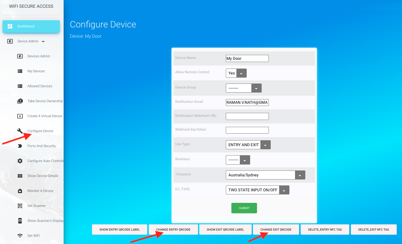
If you have installed separate doors for entry and exit, and if nobody is allowed to open or close the door either manually or by any other means other than wifisecureaccess system, the system keeps a count of the number of people within the room or building. If any of the door is for entry as well as exit (ENTRY/EXIT), you can install a separate QRCodes or NFC tags for entry and exits, instead of using the same tag for both. You can print the QRCode labels for entry as well as exit in the 'Configure Device' menu. Click on 'Configure device' under Device Admin in the dashboard menu (Fig 38C).
Fig 38C: Configuring Exit Tags for an ENTRY/EXIT door/gate
If this device usage is ENTRY/EXIT (meaning, used for entry as well as exit), you will see two separate QRCodes and NFC tags on this page. At the bottom of this form, you will also see links to print these labels. You print the Entry QR label and place it at a location that the people can scan when entering. Place the Exit label at a location where the people can scan when exiting. in Configure Device page, set 'Allow Remote Control' to 'No' so that nobody (other than the owner) can operate this door from remote. Make sure that the 'Allow Remote Control' is disabled on all doors of this building/office which are used for entry as well as exit. By doing so, the only way the users (other than the owner) can open these doors is by scanning the code at the door and not from remote. With this configuration, the system will keep a count of the number of people within the room/building/office. Note: The device_group is the same as the room or building and you could set device_group_name as the same as the room or building name
If you are using NFC tags, you need to get an NFC tag, and enter its UID as per the steps given in Section 3.9 of this documentation.
To display the number of people currently in the office/building (Device Group), click on 'Devices Groups' under under 'Device groups' in the dashboard menu. You will see the occupancy in all the groups that you have created as shown in Fig 38D. Note: Occupancy will be displayed only if you have at least one group configured with either separate doors for entry and exit or separate exit tags for exit on ENTRY/EXIT doors. Also, note that the accuracy of this depends on several factors such as 1) No one should be using any other means other than wifisecureaccess App to open/close the door/gate. 2) Remote access to open or close the door/gate must be disabled on ENTRY/EXIT type of doors/gates, and 3) Not more than one person enters or exits with one command to open or close. You can re-correct this number any time manually by editing this field.
Fig 38D: Displaying Occupancy in an Office/Building
4.7 Group Use Records
The system keeps record of the use of all the doors/gates of this group. At any time, you can see who used this group at what time. To see the group use records, click on 'Group Use records' under "device groups' in the dashboard menu. If you have created multiple groups, you will be prompted to select the group. Once selected, you will see a page similar to Fig 38E.
You can download these use records to your computer, if you want to do so for keeping any records, or for analysing the data. To download, click on 'Download Group Use records' under Device Groups in the dashboard menu. There you can provide the dates between which you want to download the data. Leaving any of these dates will take that date as open-ended. Leaving both dates as blank will download all the available use records for the past 30 days.
You can also add a program in any of your applications to download these records, and do analysis. These use records can be read using a python program. Refer to section 7.2 of this documentation.
Fig 38E: Group Use records
5.0 Scheduling Timer Actions
WifiSecureAccess system has the features to schedule actions either to execute once or to repeat daily or weekly. By configuring appropriately, you can schedule an action to open the garage door at a pre-set time of the day either once, or on a daily or weekly basis. This section explains how to do that. To schedule actions, the device must be running firmware version 4.4 or above. Upgrade the firmware, if it is not running version 4.4 or above.
5.1 Schedling actions to execute on daily or weekly basis
You can configure scheduled actions either for one time or for repeated actions either on a daily basis or a weekly basis. For example, say, you want the garage door open at 8:00 AM every day automatically. That is a scheduled action. Scheduled actions can be anything such a sending a notification email, or to open the garage or both.
To schedule an action, first make sure that the device is running firmware version 4.4 or above. Then, click on 'Schedule an Action' under Dassboard menu. This tab is also available in the main index page of the dashboard. This menu will be available if you own a device. The device cannot be virtual and your virtual devices will not be shown in the pulldown selections. Once you click on that menu, it will prompt you to select one of your devices for scheduling an action for. Once the device is selected, you will see a page similar to the following:
Fig 40: Schedule an Action
On this page, set the parameters for the scheduled action. Set the week and day of the year. The week is the Gregarian calendar week number of the year. If you do not know the week number, enter any date within that week in the format YYYY-MM-DD. It will find the week number. If you want the action to be repeated for every week of the year, leave this as * or blank. Similarly, select the day within that week. Choose it from the pull-down options. Leave it as * if you want this action to be repeated every day of that week. If you want this action to be done only on a specific day of the week, then select that day. And, if you want this action to be executed only during a specific week, enter that week number.
Note: If a week number is given, the scheduled action will be deleted at the end of that week, and will not repeat the same week next year.
Then, set the time of the day when this action to be executed. The time must be in 24Hr clock in the format hh:mm.
If you want a notification email to be sent at this time, select 'YES' for Send Email field.
Email Msg field is the message that will be sent in the email. This must be a short message not exceeding 256 characters
Next, select the Out Port. Out Port is the port to be activated at the scheduled time. You have only two options - either None or RELAY (or whatever you have renamed that RELAY port to). If you want only an email to be sent without activating anything connected to the device, select Out Port as None. If you want the garage door to be activated at the scheduled time, select the Out Port as RELAY (or whatever name that you have renamed this RELAY port to).
Then select the action to be taken at the scheduled time. Select from the pull-down options (Open or Close)
If your scheduled action is only to send a notification email, you can select out port as None.
Note: Once the garage door is opened, it will stay opened until another command is given to close it, unless AutoClose is configured. Refer to section 3.15 of this documentation for setting AutoClose.
If the sensors are not installed, the current position is not accurately known. Therefore, it will toggle the current state at the time of executing the scheduled action. So, if the door/gate is currently closed, it will open it, and if it is currently open, it will close it.
You can create multiple scheduled actions (maximum 4 per device) on each device that you own. You can see all your scheduled actions if you click on 'My Scheduled actions' in the dashboard menu. There you can delete any scheduled action. But, you cannot modify any of the scheduled actions. To delete a scheduled action, check the Delete box against the Action at the right and click Submit button. You may have to scroll the page to the right to see this Delete check box. You can delete and create a new action, if you want.
Fig 41: Schedule an Action
6.0 Integration with your other Apps and programs
WiFiSecureAccess system has web interfaces that can be used by any of your applications programs or any other Apps to open or close the garage door. From your applications, you can make an HTTPS POST call to url https://wifisecureaccess.com/devicePortsJson/ giving your credentials and the name of your device and the action to be taken in a JSON format.
6.1 Opening/Closing garage with an HTTPS POST call
To open or close the garage door, make an HTTPS POST call with the following details:
POST HTTP/1.1
Host: wifisecureaccess.com/devicePortsJson/
Content-Type: application/json
Provide the credentials and data in the following JSON format:
data = {
"email": email,
"password": password,
"device_name": device_name,
"action": action,
}
--where email and password are the email address and password of the owner of the device connected to your garage door. device_name is the name of this device. action should be either "ON" or "OFF". If you want to open the garage, action must be "ON", and if you want to close the garage, action must be "OFF".
If a POST call is made as per that above format, the garage door will be activated as per the action specified. Refer to the following sample python program. This sample call will open the garage door. Edit this code and replace the device_name, email and password with those of yours before running this program. Also make sure that requests module is installed in python using 'pip install requests' before running this program.
#!/usr/bin/env python
import requests
import json

# This uses requests module.  So, if not already installed on your computer, install it before running this program
# pip install requests
#

def main_loop():
   url = "https://wifisecureaccess.com/access/devicePortsJson/"
   #the following are just an example.  replace these with your's.
   device_name = 'My Garage'  # Replace this with the name of your device
   email = "tester@gmail.com"  # replace this with your email
   password = "12345678"       # replace this with your password
   action = "ON"  # or, action = "OFF", if you want it to put it OFF
   data = {'email': email, 'password': password, 'device_name': device_name, 'action': action,}
   headers = {'Content-Type': 'application/json', 'Accept': 'application/json',}
   r = requests.post(url, data=json.dumps(data), headers=headers)

   if r.status_code == requests.codes['ok']:
      res = r.json()
      if res['result'] and res['result'] == 'SUCCESS':
         print("SUCCESS")
      elif res['msg']:
         print(res['msg'])
      else:
         print("FAIL")

   else:
      print(r)
      print("Server error or communication error")

if __name__ == '__main__':
  main_loop()
7.0 Copying Use Records to Local Computer
Our system keeps all the use records and parking records for 30 days only. In the earlier sections (refer section 3-16 and 4-7), we have seen how to download the use records by clicking the button in the dashboard menu. If you are interested in integrating this with any of your programs, you can write a program to read the use records yourself and add that into your any applications. This helps in keeping records for longer duration. They can also use their own dedicated data analysis tools to analyze these data. A simple program making a json call to our url will provide you these use records in json format. Given in this section are some sample test program to copy these records.
7.1 Copying Device Use Records
Presented here are some sample programs showing how you can write a program to read use records and do whatever you want to do with that data.
#!/usr/bin/env python
import requests
import json
import getpass
import os

def main_loop():
   while True:
      email = input("Enter email : ")
      if email and email != "":
         break
   email = email.upper()
   while True:
      password = getpass.getpass()
      if password and password != "":
         break
   while True:
      device_name = input("Device Name: ")
      if device_name and device_name != '':
         break
   if device_name.isspace():
      print("device name cannot be empty spaces")
      exit(1)
   while True:
      start_date = input("Start Date (yyyy-mm-dd hh:mm): ")
      if start_date and start_date != '':
         break
   if start_date.isspace():
      print("start_date cannot be blank spaces")
      exit(1)
   while True:
      end_date = input("End Date (yyyy-mm-dd hh:mm): ")
      if end_date and end_date != '':
         break
   if end_date.isspace():
      print("End_date cannot be empty spaces")
      exit(1)
   while True:
      file_name = input("File Name: ")
      if file_name and file_name != '':
         break
   if file_name.isspace():
      print("Error.  File name cannot be blank spaces")
      exit(1)

   s = requests.session()
   n_next = 0
   url = "https://wifisecureaccess.com/access/get_useRecordsJson/"
   headers = {'Content-Type': 'application/json', 'Accept': 'application/json',}
   try:
      f = open(file_name, "a+")
   except:
      print("Unable to open the file %s" % (file_name))
      exit(1)

   while True:
            data = {'email': email, 'password': password, 'records_type': 'device', 'device_name': device_name, 'start_date': start_date, 'end_date': end_date, 'n_next': n_next,}
            r = s.post(url, data=json.dumps(data), headers=headers)
            if r.status_code == requests.codes['ok']:
               res = r.json()
               if res['result'] and res['result'] == 'SUCCESS':
                  if n_next == 0:
                     print("Field Names: ", res['field_names'])
                     if os.stat(file_name).st_size == 0:
                        field_names = res['field_names']
                        for field_name in field_names:
                           f.write(field_name)
                           f.write(", ")
                        f.write("\r\n\r\n")
                  records = res['records']
                  for record in records:
                     for value in record:
                        if not value:
                           value = ''
                        print(value, end=", ")
                        f.write(value)
                        f.write(", ")
                     print()
                     f.write("\r\n")
                  n_next = res['n_next']
                  records_remaining = res['records_remaining']
                  if records_remaining == 0:
                     break
               else:
                  if 'msg' in res:
                     msg = res['msg']
                  else:
                     msg = ""
                  print("FAIL: ", msg)
                  break
            else:
               print(r)
               print("FAIL:  Communication error")
               break
   f.close()

if __name__ == '__main__':
  main_loop()
And, here is a screenshot of the terminal running this program:
The above program makes a call to the server. And, it prints out the records on the terminal window of the user's computer. It also appends the same data to the specified local file. Note that it appends the data to the file instead of creating a new file so that records read earlier will not be lost. You can use the data in the file for doing any analysis of the data. The System keeps the use records for 30 days only. So, the owner of the device may read this record, say, every 15 days giving the start data and end date appropriately so that you copy the data from the last end_date. As the program appends the new data to the file, all the previously read records are also in the same file. In doing so, you will have the complete record of as many days as you want.
Note: the first line of the file will have the field names. Subsequent lines in the file are the records.
7.2 Copying Group Use Records
Group records is the use records of a group, showing who used the devices in this group and when. These records can be seen on the dashboard by clicking 'Group Records' under Device Groups in Dashboard. To copy the same records into your computer, you need a program to make calls to the IOT server. Given below is a program to do that.
#!/usr/bin/env python
import requests
import json
import getpass
import os

def main_loop():
   while True:
      email = input("Enter email : ")
      if email and email != "":
         break
   email = email.upper()
   while True:
      password = getpass.getpass()
      if password and password != "":
         break
   while True:
      group_name = input("Group Name: ")
      if group_name and group_name != '':
         break
   if group_name.isspace():
      print("group name cannot be blank spaces")
      exit(1)
   while True:
      start_date = input("Start Date (yyyy-mm-dd hh:mm): ")
      if start_date and start_date != '':
         break
   if start_date.isspace():
      print("start_date cannot be blank spaces")
      exit(1)
   while True:
      end_date = input("End Date (yyyy-mm-dd hh:mm): ")
      if end_date and end_date != '':
         break
   if end_date.isspace():
      print("End_date cannot be empty spaces")
      exit(1)
   while True:
      file_name = input("File Name: ")
      if file_name and file_name != '':
         break
   if file_name.isspace():
      print("Error.  File name cannot be blank spaces")
      exit(1)

   s = requests.session()
   n_next = 0
   url = "https://wifisecureaccess.com/access/get_useRecordsJson/"
   headers = {'Content-Type': 'application/json', 'Accept': 'application/json',}
   try:
      f = open(file_name, "a+")
   except:
      print("Unable to open the file %s" % (file_name))
      exit(1)

   while True:
            data = {'email': email, 'password': password, 'records_type': 'group', 'group_name': group_name, 'start_date': start_date, 'end_date': end_date, 'n_next': n_next,}
            r = s.post(url, data=json.dumps(data), headers=headers)
            if r.status_code == requests.codes['ok']:
               res = r.json()
               if res['result'] and res['result'] == 'SUCCESS':
                  if n_next == 0:
                     print("Field Names: ", res['field_names'])
                     if os.stat(file_name).st_size == 0:
                        field_names = res['field_names']
                        for field_name in field_names:
                           f.write(field_name)
                           f.write(", ")
                        f.write("\r\n\r\n")
                  records = res['records']
                  for record in records:
                     for value in record:
                        if not value:
                           value = ''
                        print(value, end=', ')
                        f.write(value)
                        f.write(", ")
                     print()
                     f.write("\r\n")
                  n_next = res['n_next']
                  records_remaining = res['records_remaining']
                  if records_remaining == 0:
                     break
               else:
                  if 'msg' in res:
                     msg = res['msg']
                  else:
                     msg = ""
                  print("FAIL: ", msg)
                  break
            else:
               print(r)
               print("FAIL:  Communication error")
               break
   f.close()

if __name__ == '__main__':
  main_loop()
And, here is a sample snapshot of a terminal running this program:
The above program makes a call to the server. And, it prints the records on the terminal of your computer. It also appends the same data to the specified file on your local computer. Note that it appends the data to the file instead of creating a new file so that all previously read data are retained in the file. This data in the file will help you analyse it using any of your sophisticated tools. Keep in mid that the system keeps records for 30 days only. So, you will have to copy the records, say, every 15 days or so giving the start date as the end date given when copying data last time. As the program appends the data to the same file, it will have all the previously read data as well. That way, your file will have all the records for a much longer time.
7.3 Copying Customer Use Records
Customer use records are the records of a customer's use of all the devices in the system. You can see your use records of any devices in the system in Dashboard by clicking 'My Use Records' under 'User Admin' in Dashboard. If you want the same records copied into your local computer to keep the data for longer time, or to do detailed data analysis for your special needs, you need a program to make calls to the server. Given below is a program in python to get these records from the server.
#!/usr/bin/env python
import requests
import json
import getpass
import os

def main_loop():
   while True:
      email = input("Enter email : ")
      if email and email != "":
         break
   email = email.upper()
   while True:
      password = getpass.getpass()
      if password and password != "":
         break
   while True:
      start_date = input("Start Date (yyyy-mm-dd hh:mm): ")
      if start_date and start_date != '':
         break
   if start_date.isspace():
      print("start_date cannot be blank spaces")
      exit(1)
   while True:
      end_date = input("End Date (yyyy-mm-dd hh:mm): ")
      if end_date and end_date != '':
         break
   if end_date.isspace():
      print("End_date cannot be empty spaces")
      exit(1)
   while True:
      file_name = input("File Name: ")
      if file_name and file_name != '':
         break
   if file_name.isspace():
      print("Error.  File name cannot be blank spaces")
      exit(1)

   s = requests.session()
   n_next = 0
   url = "https://wifisecureaccess.com/access/get_useRecordsJson/"
   headers = {'Content-Type': 'application/json', 'Accept': 'application/json',}
   try:
      f = open(file_name, "a+")
   except:
      print("Unable to open the file %s" % (file_name))
      exit(1)

   while True:
            data = {'email': email, 'password': password, 'records_type': 'customer', 'start_date': start_date, 'end_date': end_date, 'n_next': n_next,}
            r = s.post(url, data=json.dumps(data), headers=headers)
            if r.status_code == requests.codes['ok']:
               res = r.json()
               if res['result'] and res['result'] == 'SUCCESS':
                  if n_next == 0:
                     print("Field Names: ", res['field_names'])
                     if os.stat(file_name).st_size == 0:
                        field_names = res['field_names']
                        for field_name in field_names:
                           f.write(field_name)
                           f.write(", ")
                        f.write("\r\n\r\n")
                  records = res['records']
                  for record in records:
                     for value in record:
                        if not value:
                           value = ''
                        print(value, end=", ")
                        f.write(value)
                        f.write(", ")
                     print()
                     f.write("\r\n")
                  n_next = res['n_next']
                  records_remaining = res['records_remaining']
                  if records_remaining == 0:
                     break
               else:
                  if 'msg' in res:
                     msg = res['msg']
                  else:
                     msg = ""
                  print("FAIL: ", msg)
                  break
            else:
               print(r)
               print("FAIL:  Communication error")
               break
   f.close()

if __name__ == '__main__':
  main_loop()
And, here is an example snapshot of a local terminal running this program.
The above program makes a call to the server. Refer to the suggestions given for reading group records in the previous section about copying records. Those comments apply here as well.