Garage Door/Gate Controller
Bhadre Access Control Systems - An Introduction
Bhadre access controller is a smart controller that can be used for controlling and managing access to any restricted or public areas. The restricted areas can be a house, office, building, garage doors and gates, or anything similar. It can also be a private parking lot of an apartment complex or office. Public areas are public parking lots (paid or free), public transportation systems, cinema halls, GYMs, caravan parks and so on. Bhadre access controller can be integrated with any of the existing controller. With this integration, one can use his universal ID card, smartphone, QRcode or fingerprint to open/close a gate or a door. One can also use Google Home, Google Nest, Google Smart Home or Amazon Alexa to operate the door/gate. The doors/gates can be operated from anywhere remote. One can also know the current status of the door/gate (whether open or closed) from remote. Notifications can be configured to send if the door/gate remains open for a long time. If it is a garage door or gate, one can configure AutoClose such that the garage door/gate gets automatically closed after a pre-configured delay. Multiple users can be authorized to open/close the door/gate. The owner of the controller can revoke this authorization any time. It is also possible to configure the door/gate such that the authorization gets automatically revoked after a date/time. In addition, one can configure open and close times such that only between these times the authororized persons can access the door/gate. It is also possible to set authorizations such that some people are allowed to use only during some specific time period on pre-configured days of the week. Two factor authentication such as pin or fingerprint can also be optionally configured in places where high securtity is required. Entry to a public place can also be controlled based on age, gender or citizenship. When used for paid parking lots, public transport, or cinema halls, entry fees are charged automatically and debited to their credit card using Stripe system. Booking a place or holding a place in public places such as cinema halls and parking lots are also possible. This documentation describes how the smart controller can be installed and how the smart device can be configured to meet all the needs.
Bhadre provides two different access controllers - one for using with Garage Doors and gates and 2) for using with doors of buildings, offices and houses.
This document is for the Garage Door/Gate Controller
1 Garage Door Gate Controller
For controlling a gate or a garage door, the controller used is this one with the details shown below. It is a small unit with dimensions 53mmx53mmx25mm. It has a USB-C power port and a 2-pin JST socket to use a JST cable to wire it to garage door/gate.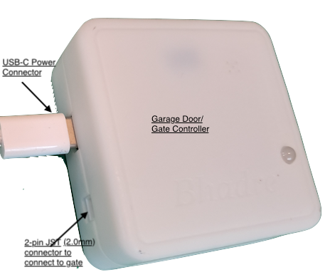
In this document, we will describe how this controller can be installed on a gate or a garage door. This controller can be used with garages that have manual push button and those do not have manual push buttton, but has a wall mounted remote to open and close. Some of the gates may have two push buttons - one for opening and another for closing. This controller can be used with all such garages and gates rregardless whether it has just one push button or separate push buttons for open/close.
2 Integrating Smart controller to existing garage doors or gates
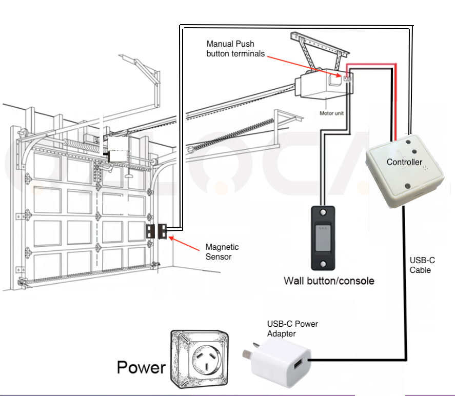
This garage door/gate controller is a cloud based one that connects through WiFi to the interenet. The controller can be cabled to any automatic garage doors or gates. There are two ways of connecting this your garage door or gate... A) by connecting the two wires from the 2-pin JST connector of this controller to the two terminals of the push button of the remote of the automatic garage door or gate, or B) By connecting the 2-pin JST connector on the side of this controller to the manual push button terminals of your garage door or gate using the supplied 2-wire cable. The 2-pin JST connector of this garage door/gate controler is as shown in the picture below.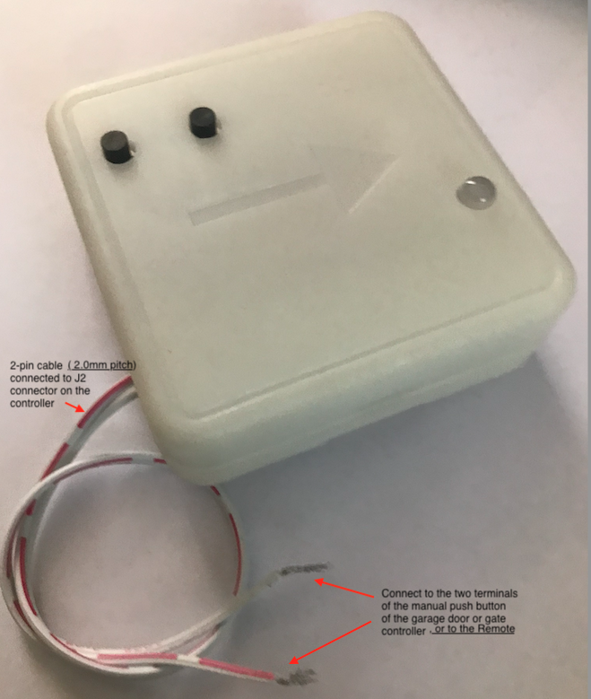
4) Cabling to a remote of your garage door/gate
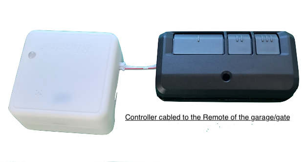
When you purchased thre garage door controller from Bhadre, a universal remote is included in the package. It is a pre-wired 3-button remote. The following is a picture of that remote.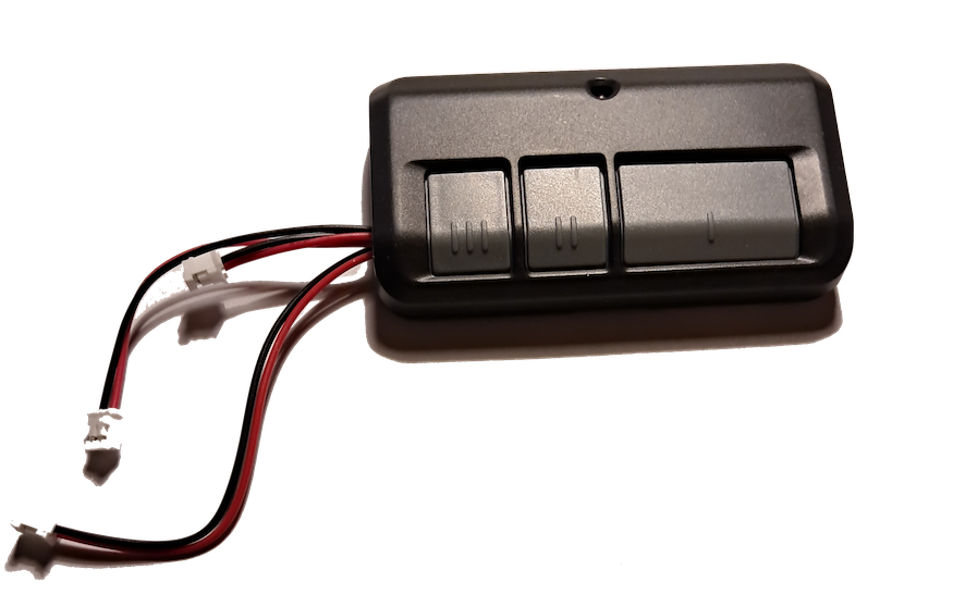
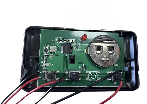
This is a pre-wired remote. The following pictures show how three JST (2.0) cables are soldered to the three push button terminals within the remote.
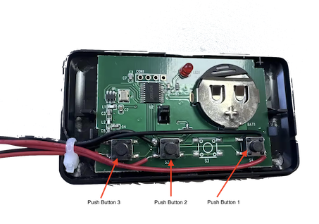
There are three cables coming out of it, each of them at different length. Each cable is wired to one of the the three push buttons within the remote.
Each one of these unoversal remote can operate three different garage door or gate. Coonect the three cables to three different WiFi controllers from Bhadre. If you have only one garage door, you need to connect one of these cables to one WiFi controller from Vhadre.
Once cabled, pair the remote to your gate or garage and configure the WiFi controller from Bhadre. You can pair this with your garage as per the steps below. Configuring the WiFi controller is explained in the sections below.
If you do not want to use the included universal remote, or if that does not work with your gate or garage, you can cable your own remote the way shown in the pictures above
If you want to use your own remote, can do so.
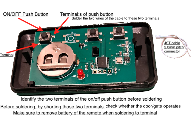
Note: Note: This needs soldering work. Make sure to remove the battery of the remote when soldereing. You may have to drill a hole on the plastic box of the remote to take the cable out to connect to the controller.
Steps to pair universal remote to your garage door or gate
It is recommended to try pairing the universal remote with your garage door first before attempting to cable it to WiFi controller from Bhadre.
First make sure that the remote has the battery, and it is charged. LED of the remote will be Red if it has battery. LED will turn dim and may show rapid flashes when battery is low and needs replacement. Use 3V CR2032 coin cell battery when replacing
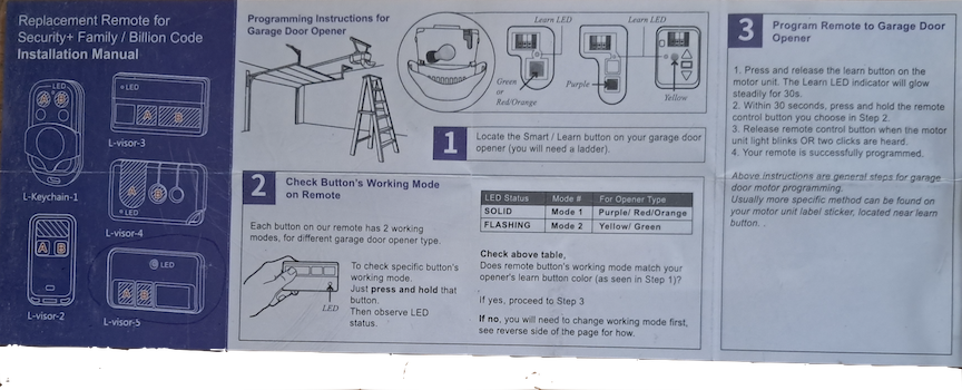
Refer to the following document for instructions for pairing:
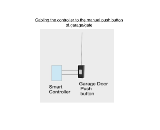
B) Cabling the controller to the two terminals of the manual push button of your garage door/Gate
In this second method, you connect the two wires from the controller to the two terminals of the manual push button of your garage door or gate.
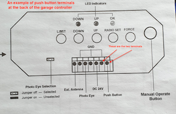
In order to integrate the smart controller to your garage doors or gates, you need to locate the two terminals of a manual push button on your existing garage door controller. There are plenty of manufactures of garage doors and gates and, therefore, the controller of those garage doors and gates can come in various designs. However, all of them will have a manual switch (push button) to open/close. These pushbuttons may either be located on the PCB of the garage, or it may be mounted on the wall or elsewhere in the garage. On some garage door/gate controllers, you may find two terminals on a terminal block on the main controller marked as 'Push Button'. Here are some example pictures:
Note: Some well-known garage doors and gates do not have any manual push button to open them. Even the push button mounted on the wall may be a remote. In such cases, the method described above of cabling to the remote is the only option to integrate Bhadre Access control system to these garages or gates.
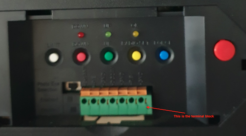
Here is another garage door controller from another manufacturer:
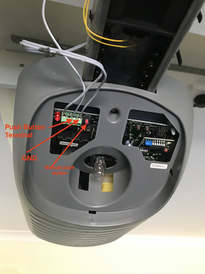
Or, in some cases, you may find a push button on the wall.
You can cable the smart controller to either the push button terminals on the main controller, or to the two terminals inside the push button on the wall (if it is a two-wire manual push button). Test manually before cabling the smart controller to the push button terminals to confirm that this is compatible. To test it manually, short between the two terminals using a bare wire. You should be seeing the garage door either opens or closes. If so, this is compatible to the Bhadre smart controller
If the garage door/gate is compatible, cable the Bhadre smart controller to the push button terminals of the garage door. Connect the two wires from 2-pin JST cable of the controller to the two terminals of the push button of the garage door/gate. Mount the controller anywhere convenient, preferably close to the pushbutton terminals (either on the wall, or near the terminal blocks on the garage controller).
Gates with two push buttons - one for Opening and another for Closing
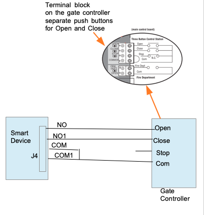
There are some gates with two separate manual push buttons - one for opening and another for closing. In most of those cases, the gate's controller usually closes the gate automatically a few seconds after it is opened. In those cases, smart device needs to be cabled to the Open terminals of the gate controller, as closing is done automatically a few seconds after opening.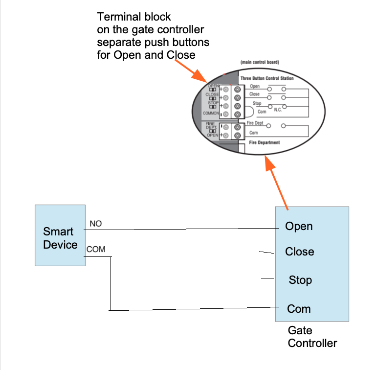
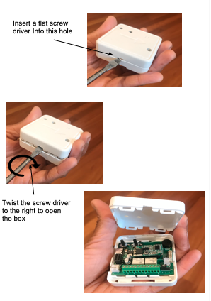
However, if you want the smart device to open as well as close that type of gate, the cabling of the smart device to the controller of that gate has to be done differently. We will cable four wires of the controller to four termials of two push buttons of the garage door/gate. To get access to the four terminals within the controller, you need open the box of the controller. The controller can be opened by using a flat screw driver as shown in gthe pictures below. It is very rarely that you will find a need to open its box. For garages and gates with single push button for both opening aand closing, there will never arise a need to open its box. You can use a flat screw driver to open the box as shown in the pictures below.
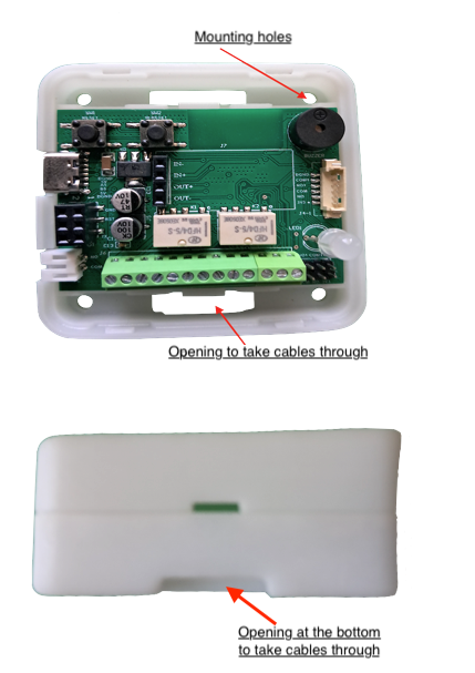
Pictures below show all the connectors and the labels on each connector. These will help when cabling and installing the controller.
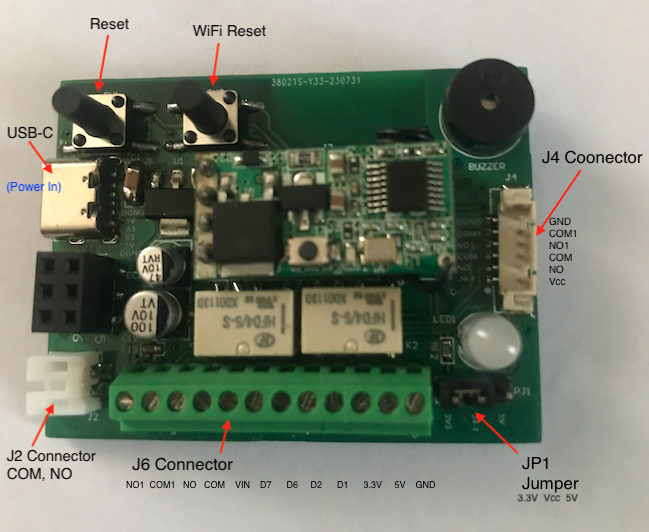
NO, COM, NO1 and COM1 on the green connector of the pcb board inside the controller are the four terminals. Note: COM and NO on this freen connector are the same as the two pins (wires) of the JST connector.
Connect COM and NO to the two terminals of the 'Open' push button and COM1 and NO1 to the two terminals of the 'Close' push button. In this figure, the picture of the gate controller board is from the installation manual of a Lift Master gate available in USA. For any other similar gates, look for these Open and Close terminals on its controller board.
Note: For this to work, the parameter 'Separate ON/OFF Button' must be set to 'Yes' in 'Ports and Security' menu under Devices Admin in Dahboard. Refer to the settings of Ports and Security as explained in the document "Initial and Common Configurations".
3 Installling Tilt Sensors on Sectional Garage Doors
Note:Installing sensors on doors and gates is optiona. The doors and gates can be operated even without the sensor. A sensor helps in knowing the current position of the door/gate (whether open or closed) from remote accurately. Installing a sensor also helps in sending notifications if thedoor/gate remains open for a long time.
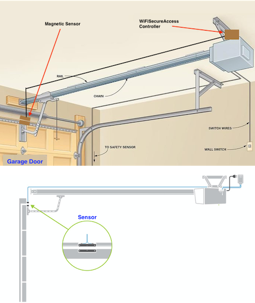
If the garage doors or gates are opened manually or directly by its remote, the current position of the gate can go out of sync within the controller. If one has to know the current position of the gate accurately from remote, it is important that the controller knows the position correctly even when the gate is opened by any other means. To achieve this, it is recommended to install a position sensor on the garage door/gate. There are multiple types of sensors that can be installed ... 1) A tilt sensor for vertical sectional garage doors, or 2) a magnetic sensor for any kind of doors/gates. Note that this step of installing sensors is optional. However, if you need to know the position of the door (open or closed) accurately from remote, or to send notifications when the door/gate remains open for a long time, installation of sensors is required.
Shown below is a picture of a Tilt sensor. This can be purchased along with the garage door/gate controller.
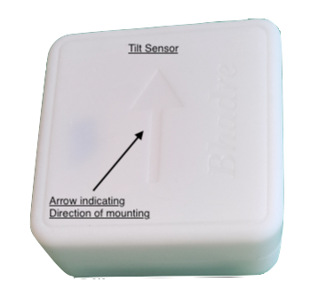
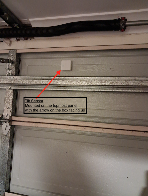
Install this on the top-most panel of the sectional garagec door. You can either use a two-sided tape or screws to install this. Install it such a way that the arrow marked on the box is facing up when the garage is fully closed. No pairing of this to the controller is required as it comes with paired.
PS: In order for it to use the sensor to detect the current position of the door/gate, not only that you have to install the sensor, but also you have to set the field "Door Sensor Connected" in the menu 'Ports and Security" under Device Admin in the Dashboard (as explained in the document "Initial and Common Configurations").
4 Installling Magnetic Reed Sensor on garage doors or gates
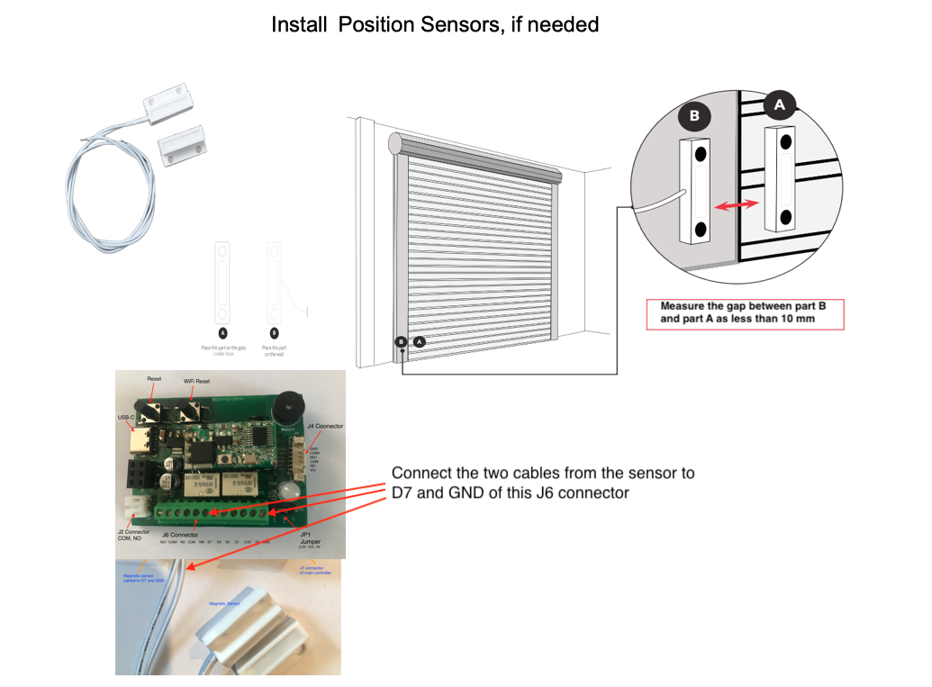
This is also optional as explained above. Purchase a magnetic reed sensor from Amazon or eBay or from our site that has 1 to 3cm sensing range. Purchase the one that has NO and NC outputs to have maximum flexibility in installing.
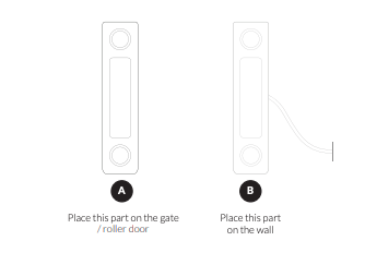
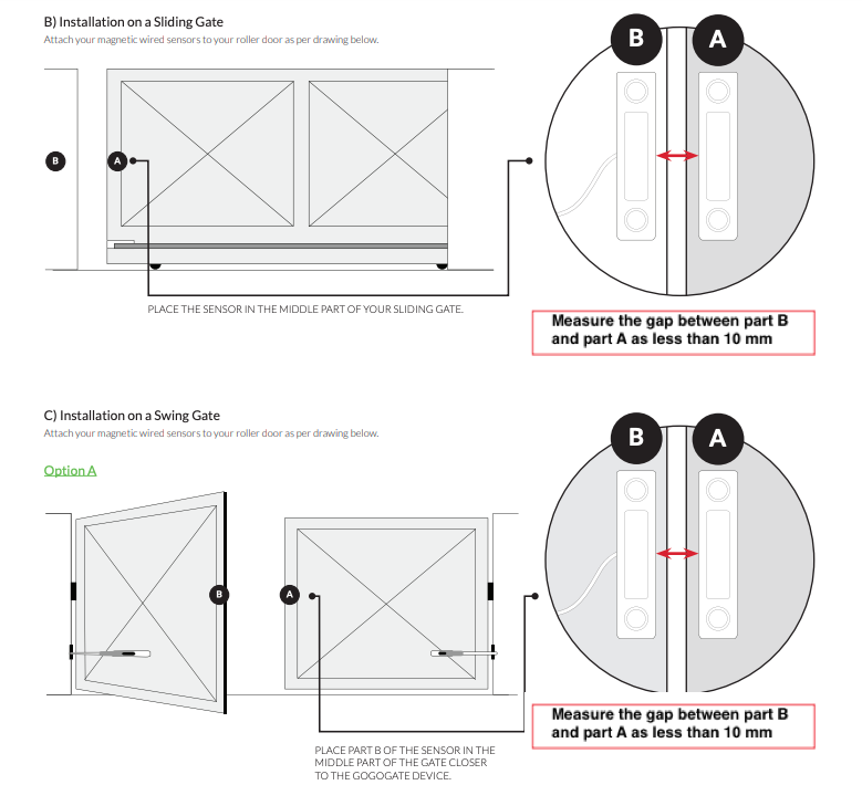
There are two possible locations on the garage/gate this sensor can be installed... 1) At a location on the door/gate where both parts of the sensor cane be aligned (both psrts A and B come close to esch other) when the garage/gate is fully closed, and 2) at a location where both part A and B of the sensor align themselves when the garage/gate is fully open. Choose either one of these methods depending on your convenience. Usually, it is easier to install at fully open position because the sensor can be closer to the controller and, thereby, short cable is enough to connect sensor to the controller, if controller is sitting on the top of the motor of the garsge/gste.
Install the sensor such that the two parts (A and B) of the sensor align themselves (within 10mm space between them) when the garage is closed or open depending on the location you have chosen to install. If you have chosen to install at the fully closed position of the garage/gate, install such that both parts A and B of the sensor align themselves when the garage/gate is fully closed. If you have chosen to install at fully open position of the garage/gate make sure that it is installed such that both parts A and B align themselves when the garage/gate is fully open. Fix them such that the gap between part A and Part B is around 1cm when they both align themselves.
Once installed, cable sensor to the controller. If the sensor is installed at fully closed position, Cnnect NO terminal of the sensor to D7 terminal (on the green connector on the PCB of the controller), and GND terminal of sensor to the GND terminal on the green connector of the controller. On the other hand, if you have installed the sensor at fully open position of the garage/gate, connect NC terminal of the sensor to the D7 terminal of the controller, and GND of sensor to GND terminal of the controller.
Fix the part (Part B) on the fixed frame and the other one (part A) on the moving part of the frame of the garage. The following are some pictures that will help you install this. Note: Both the parts of the magnetic sensor have double-sided mounting tape at their back. So, you can mount it anywhere convenient, and no screw is required.
Note: You can also install it such that the two parts align with each other when the garage is fully open. If you do so, make sure that you cable NC and COM to D7 and GND of the sensor to the controller.
If you install sensor such that the two parts of the sensor A and B align with eatch other when the garage door is fully closed, then cable NO and COM of the sensor to D7 and GND of the controller.
Then cable the sensor to D7 and GND (on the green connector inside the box) of the smart device (with one terminal of the sensor D7 and the other terminal to GND on the smart device).
After installing the sensor, you need to test if it is working properly. In the document on "Initial and Common Configurations", you will see how to check if the sensor is currently ON or OFF. The sensor must be ON when the garage/gate is closed and OFF when it is open.
PS: In order for it to use the sensor to detect the current position of the door/gate, not only that you have to install the sensor, but also you have to set the field "Door Sensor Connected" in the menu 'Ports and Security" under Device Admin in the Dashboard (as explained in the document "Initial and Common Configurations").
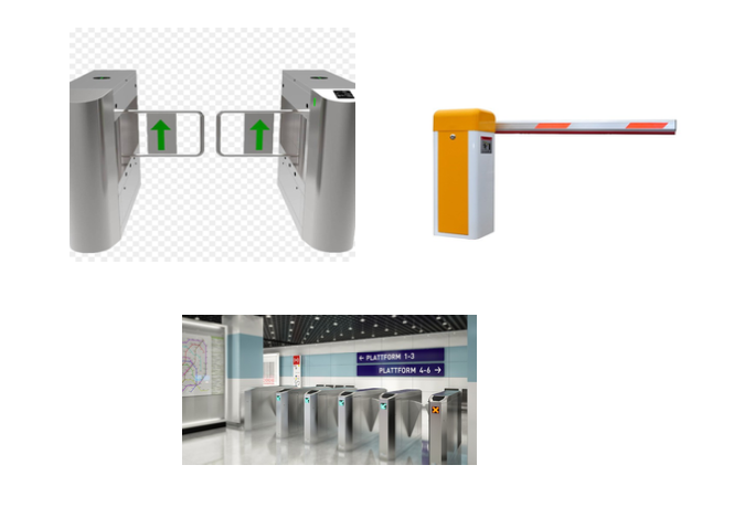
5 Integrating with a Boom Gate or any similar gate
If this is a parking lot, or any public access place with a boom gate or any similar gate with its own controller, Bhadre controller can be integrated with it. Most of those boom gate controllers will have a manual push button terminal to manually operate the gate. Either a push button is already connected, or one can connect a push button to those two terminals. If so, by pushing that push button, one can open or close the gate. Once you locate those two terminals of that push button, you can cable the RELAY terminals COM and NO of the Bhadre controller to those two terminals of the push button. That is all what is needed to integrate Bhadre controller to a boom gate or any similar gate.
If these controllers are used in a parking lot or any public places, you need to interface Bhadre controller to every gate of the public place or the parking lot. The controller can be installed anywhere secure so that nobody other than the owner can access it. Then, run cables from that to the boom gate controller. It is important that WiFi is available at the location where the controller is installed. Install the scanner (or just the QRCode or NFC tag) anywhere convenient for the public to scan when entering the public place or parking lot. You can print additional QRCode, if you want, as per the instructions given in the document "Initial and Common Configurations".
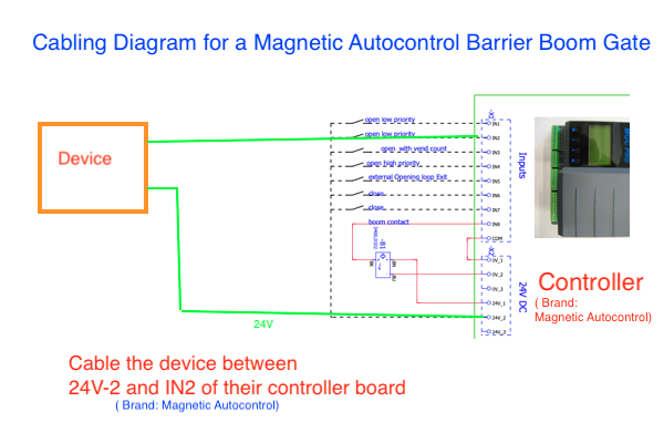
The pictures below show how the Bhadre controller can be cabled to a boom gate.
Fig 51A below shows a typical cabling diagram for a Magnetic Autocontrol barrier boom gate. Magnetic Autocontrol is one of the available barrier boom gates used by customers. For any other make and model of boom gates, refer to their User Manual to find the trigger points to connect the device to.
6 Attaching a manual over-riding pushbutton to activate the output port
If you want an over-riding manual pushbutton to open or close the garage door/gate, you can cable one to the controller. Cable the two terminals of the external push button to D1 and GND terminals on the green terminal connector on the PCB inside the box of the controller. Once cabled, pressing the push button will activate the garage door/gate. This push button can be used for opening the gate to exit only so that there is no security issue. Keep in mind that this push button does not check any permissions and so, anyone who has an access to it can open the garage/gate. Therefore, it can only be place at a location for exiting.
Note: In garage door/gate controller, if you are cabling an ultrasound sensor to this controller, push button cannot be cabled, as D1 port is needed for both.
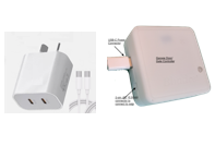
7 Applying Power to the Controller
Once the controller is installed, it is time to power it on and do the needed configurations. The gate/garage door controller takes 5VDC power through its USB-C connector. So, use a USB power adapter and cable it to the USB-C connector of the controller using a USB-C cable.Note: Power can be applied at +5V and GND terminals of the green connector inside the box, instead of applying through the USB connector.
8 Initial Setup and Common Configurations
In order to use this garage door/Gate controller, the controller has to be configured. This initial configuration can be done either before or after cabling it to the garage/Gate.Follow the steps given in the document Initial and Common Setup and Configurations to do the initial configurations of this controller prior to using it.
9 Enabling Sensor, Enabling Notifications and Setting Duration to keep the Door/Gate open
Note: Described here in this sub section is the way to enable/disable notifications based on sensors installed on the door/gate. This is different from the type of notifications described in section 18 "Configuring Notifivcations when a device is activated" in the document "Initial and Common setup and Cofigurations"As mentioned earlier, installing and enabling sensor is optional. However, without the sensor enabled, the current position of the door/gate (open or closed) that you see in the app or a browser may not be correct. If you also operate the door/gate either manually or by any other remote control, or if someone keeps the door/gate open, Bhadre system will not know about it unless the sensor is enabled. So, in the absence of the sensor, what you see as the current position (open or closed) on the app or browser may not be correct.
Also, in order to send notifications, or to sound buzzer when the door/gate stays open for a long time, you need to install the tilt sensor or the magnetic sensor on the door/gate and cable it to the smart controller as explained earlier in this documentation. Check if the sensor is working before enabling notifications. You can see whether the sensor is currently ON or OFF by clicking 'Device Details' under Device Admin in the dashboard menu. Then click on sensor Values. Check if it reads ON when the door is closed and OFF when door is open. If it is not working, check the cabling and the gap between the two parts of the magnetic sensor (within 10mm in the closed position of the door/gate).
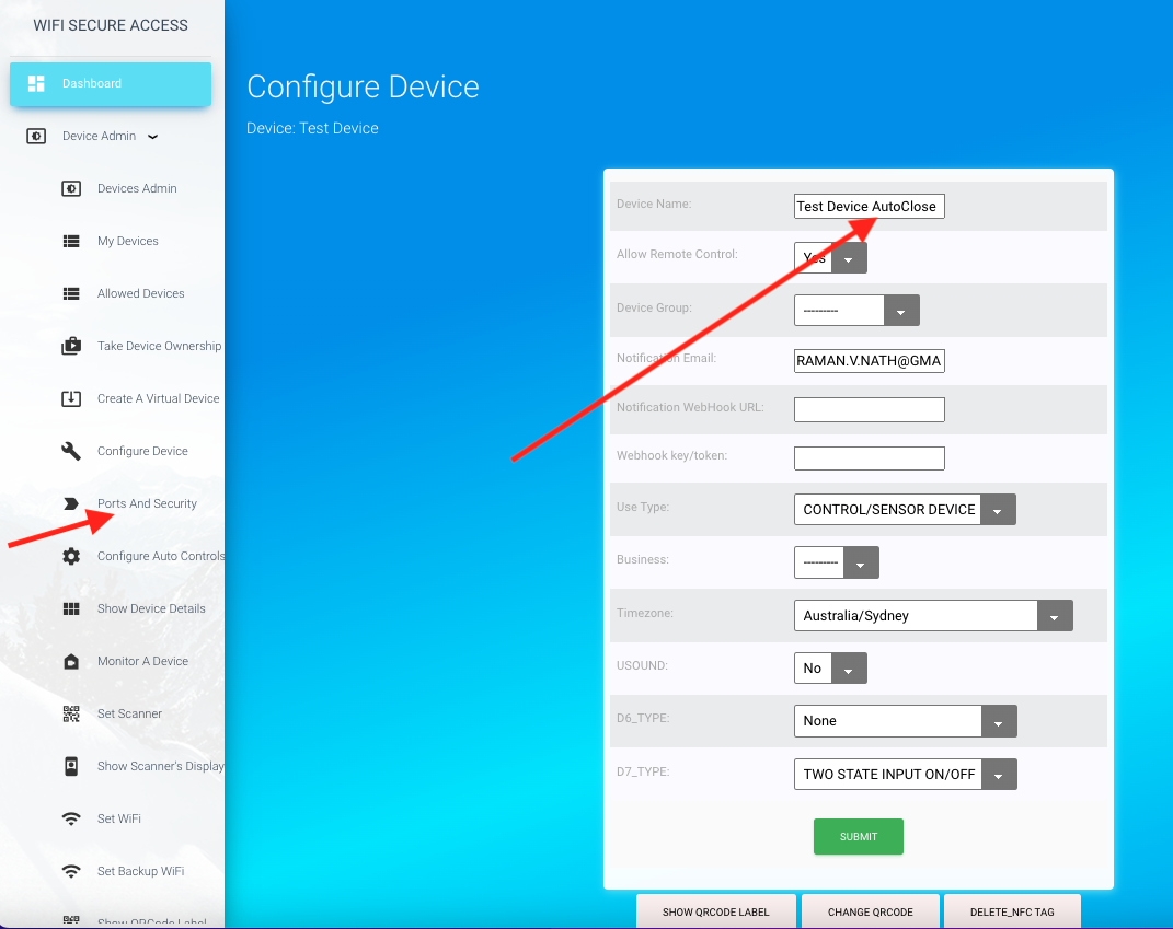
If you have installed sensor, check and make sure that D7_type in the device configuration is selected as "TWO STATE ON/OFF". To do that, click on "Configure Device" under Device Admin in the dashboard menu. That will open a page as shown below.
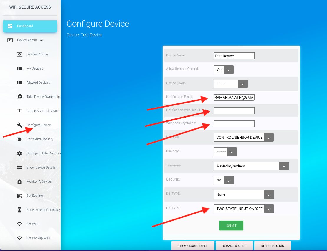
On this page, you should be seeing D7_type as TWO STATE ON/OFF. If not, select it as TWO STATE ON/OFF and press submit.
On this same configuration page, you can set the fields for sending notifications. Notification Email field shows the email address to send email notifications. By default, this is set to the email address of the owner of this device. You can change it to any other email address, if you want. If this email field is left blank, no emails will be sent.
The fields Notification Webhook URL is the URL of your webhook to which a call will be made when conditions are met to send notifications. Webhook key/token is the key or the token of your webhook. You may enter those in these two fields, if you are interested in making such calls to send notifications. If the Webhook URL is left blank, it will not make any such calls to webhook URL. The call is an HTTPS POST call with the key token in the header ('Authorization': webhook_key), and with some data in the body in JSON format. The data will have the device name, sensor_name, current value of the sensor, and a message. The following is the type of call that will be made:
HTTPS POST call
url: The Notification webhook URL configured
headers = {'Authorization': webhook_key, 'Content-Type': 'application/json', 'Accept': 'application/json',}
data = {"controlDevice": control_device, "sensorDevice": sensor_device, "sensor": sensor_name, "message": msg_webhook, "currentVal": current_value, "limitSet": limitVal, "msg_code": msg_code}
requests.post(notification_webhook, data=json.dumps(data), headers=headers)
Next, the notifications have to be enabled such that it sends notifications when the garage door stays open for a long time. It is also possible to configure it to sound an alarm (buzzer) either once or repeatedly when the garage stays open.
To enable notifications, sensor has to be installed to sense the current position of the door. Installing sensor is explained in section 3 and 4 of this documentation above. Once sensor is installed, click on 'Ports and security' tab under Devices Admin page. Then set Yes in the field "door sensor connected' and press Submit button. Then, to enable notifications, click on Configure Auto Controls under Device Admin in the dashboard menu. That will show you a page similar to the following.
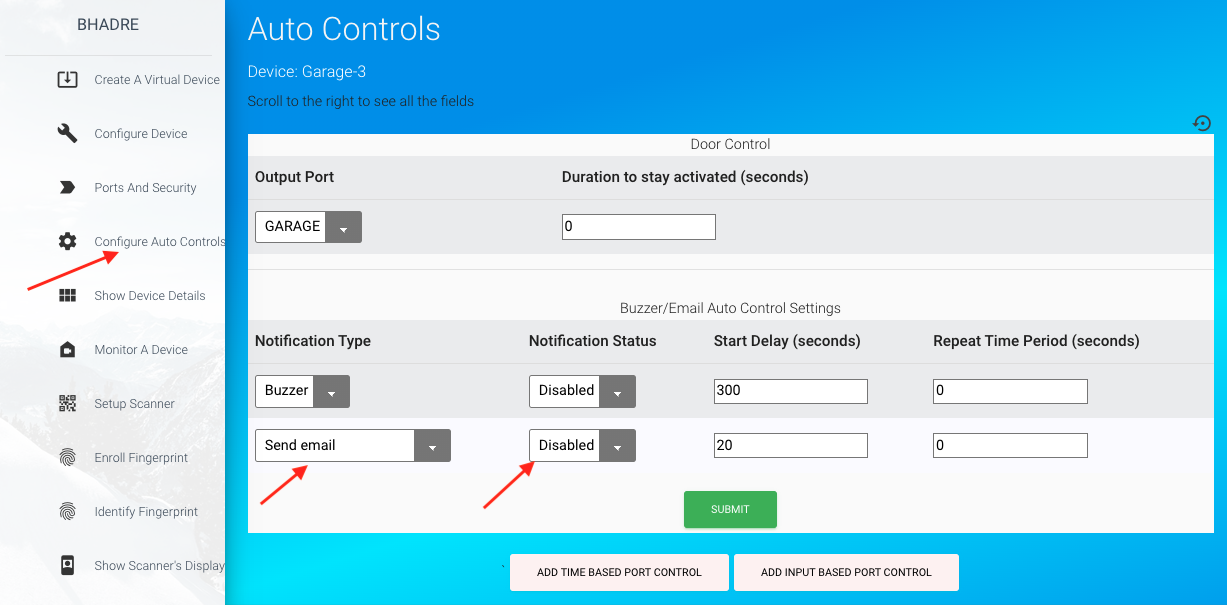
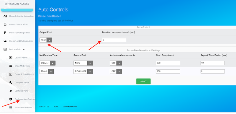
On this page, you will see three rows of controls. The first row is about auto close. A garage door or gate (other than parking gate) is assumed to be not in AutoClose by default. In other words, they do not close by themselves after opening, unless AutoClose is set. The field 'Duration to stay active' in the first row of controls on this page is the duration the garage door will stay open when in AutoClose mode. A value of 0 means that it is not in AutoClose mode. If it is in AutoClose mode, you can set it to anything that you like. This value is ignored when it is controlling a garage or gate which are not in AutoClose. More about that can be found in the document "Configuring Auto Controls".
To send email notifications or to send a webhook call when the door/gate stays open, you need to set the next two rows on this page. The last row on this page is the setting for sending notification. To enable notification, select notification type (the first column of this control). Then click on 'Notification Status' in the last row of this page and select 'Enabled'. Then set the delay time. This is the time it will wait to send notifications or to sound buzzer since the garage was opened. If you want the notifications to be sent periodically when garage stays open, you can also set the 'Repeat Time Period' in seconds.
Similarly, if you want the buzzer to sound, you can select 'Notification Status' as 'Enabled' for the row corresponding to BUZZER (last but one row in Fig 126). Here also, you can set the delay time and time period of the alarm as you desire. Note that, normally the defaults will work.
To enable notifications, sensor must be cabled, and 'Door Sensor Conned' field in 'Ports and security' menu must be select to 'Yes' prior to coming to this page to enable notifications.
10 Configuring Auto Close for gates and garage doors
By default, garage door will not close by itself after opening. So, you will have to manually close it any time after opening it. With Bhadre smart controller, it is also possible to configure auto-closing of the garage door. For example, say, you want the garage door automatically closed 2 minutes after it is opened. This can be done by appending a word AutoClose in the port label of the port of the smart device connected to garage door controller. To configure this, click on 'Configure ports' under Device Admin in the dashboard menu. Then change the name of the relay1 Label from 'GARAGE' to 'GARAGE AutoClose'. Then press submit.Note: The word AutoClose is a single word, case insensitive.
Next, you need to set the duration for which the garage door should remain open before closing it automatically. Click on Configure Auto Controls under Device admin in the dashboard menu. Then in the first row, change the value of 'Duration to stay activated (sec)' to whatever you prefer. If you want the garage door to remain open for 2 minutes before closing, then set this to 120. Press submit.
Note: This first row of control on this page has no effect if AutoClose is not set. The field 'Duration to stay active' is used only if AutoClose is set. So, if AutoClose is not set, The value in this field can be anything, but usually reset to 0.
Note: The duration is the time since you press the button to open the garage and not the time since the garage door comes to a full open position. So, make sure not to set this duration lower than the time needed for the garage/date to come to a full open position.
With the above configuration with AutoClose, the garage will automatically get closed two minutes after it is opened. With this autoClose in place, suppose that you want to keep the garage remain open anytime after you open it, you can use either Google Home or alexa, and say 'Hey google, Open *name of the device* during the time the garage is open. So, if you try to do so during the period when the garage is open (when in autoclose mode), it will cancel autoclose and will stay open. You can also do this by activating the device using the app when the door/gate is in open position. Then, if you want to close the garage, you can say "Hey Google, Close *name of the device*". Or, alternatively, activate the device using the app. This is a special handy feature of our smart device that you can configure and use.
PS. Make sure that the firmware of the device is 4.5 or above to get all the latest features of AutoClose. Update firmware if current firmware is less than 4.5
PS. It is assumed that the cabling of the smart device is to the push button terminal of the garage door controller or its remote. The smart device applies a pulse to it for opening or closing. If you are using it for opening a gate or door where it needs anything other than a pulse, this AutoClose feature will not work. In that case, you may be needing the Door controller. Please Contact us for any help
11 Configuring Scheduled Actions or Additional Automatic Controls
This controller and mostly all the controllers from Bhadre have powerful features to configure automatic controls either based on sensor, or periodic, or based on sensors or other events on any other remote devices. External sensors can also be cabled to this controller as explained in the document Cabling External Sensors
Refer to Configuring Automatic Controls to configure automatic controls as well as scheduled actions. Some of the automatic controls that you can configure are opening or closing the garage/gate automatically regularly at some time of a day or a week
12 Allowing others to use this controller and putting restrictions on their access
If this device is controlling a gate or door of a restricted private access, the owner of this device/property has to set who can access this. The owner can allow as many people as he wants. If this is a gate/door of a public access place, anybody can open or close the gatae/door. But, the owner of the device/proiperty can set at what time people can access. In both cases, additional controls can also be configured to allow based on the profile of the person. For example, one can configure such that only females are allowed, or only people above the age of 18 are allowed, and so on. For details on how to configure these access controls, refer to the document Allowing Multiple Users13 Monitoring a door or gate from Remote in Real Time
Access through any door or gate can be monitored from remote on real time by the owner of that device or by those whom the owner has permitted. That will help to know who is passing through that door or gate in real time. To monitor, click on 'Monitor a Device' under "Devices Admin' in the Dashboard menu. It will prompt for the device name. Select it from the pulldown menu. Only those devices in parking_lot/Public place and those in access control mode with assigned device group will be seen in the pulldown menu. You may also have to select the display mode. There are two ways to display the details of the person who opens/or closes a door or gate. 1) scrolling mode and, 2) profile photo. In scrolling mode, it will display the email address of the person and will scroll down when a new person opens/closes the same gate/door. Ther screen will show all the previous persons opened/closed this door/gate. This window will be scrolling down when a new person opens or closes. In 'Profile photo' mode, it will display the detailed identity of the person including his/her profile picture (if the person's profile picture is in the system). Once selected, it will open a browser window. The window will be empty initially with just a title displayed. If you keep this window open, you can see a new line appearing whenever a user either opens or closes that door/gate. You will also hear a beep sound whenever that happens. If this is a parking lot, it will display the Vehicle registration number. It will also display whether this is an entry or exit. The display also has a count at the top showing the number of users in that place since you started monitoring. This number is the toal number entered minus the total number that exited. If this door/gate is an entry gate only, there will not be anyone exiting it, and vice versa. However, if this gate is for entry as well as exit, the total number displayed is the total entered - total exited. Opening a door/gate from remote will be displayed as Entry/Exit and will not be counted in the number displayed.
i
This remote monitoring becomes very useful in event halls and public places. Along with this, if entry controls are configured, the system can restrict the people who are not authorized to enter. These setting are described in the document "Allowing others to use your device"
13 Device Use Records
The system keeps record of the use of this garage door for 30 days. At any time, you can see who used this garage door and at what time. To see the use records, click on 'Device Use records' under 'Device admin' in the dashboard menu. You will see a page similar to the one in Fig 137 with two columns (User and use_time).You can download these use records to your computer, if you want to do so for keeping any records, or for analysing the data. To download, click on 'Download Device Use records' under Device Admin in the dashboard menu. There you can provide the dates between which you want to download the data. Leaving any of these dates will take that date as open-ended. Leaving both dates as blank wi ll download all the available use records for the past 30 days.
You can also add a program in any of your applications to download these records, and do analysis. These use records can be read using a python program. Refer to sub-section 6 of Integrating with other Apps and Programs.
15 Device Configuration Menu
In addition to the ones explained in this document, there are many other configurations that are common to all types of devices of Bhadre. Any of these configurations that you have done can be changed any time when need arises. There are several product-specific configurations that you will do later when need arises. For example, if this device is a scanner, there are specific configurations required. Many of them are explained in document Initial and Common Configurations. All the menu for configuring a device will be found in Devices Admin under Admin Dashboard. Have a look at the Devices Admin menus that you may need later depending the product that you purchased and depending on your application of that product.