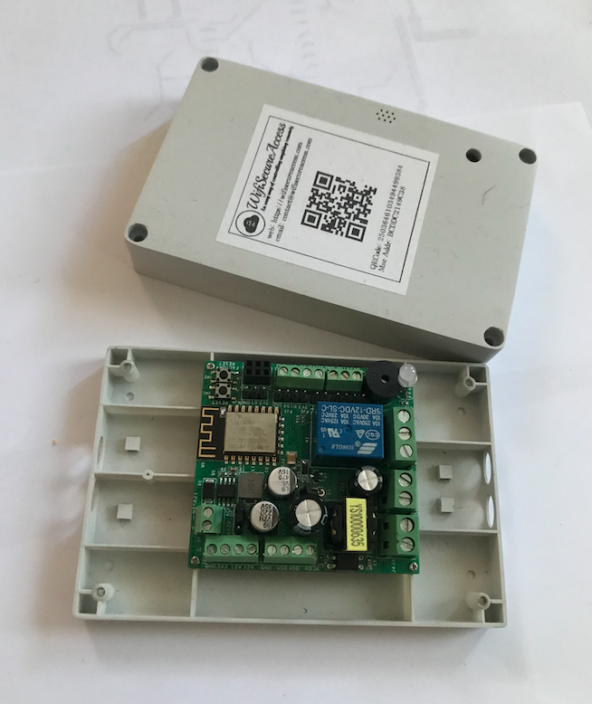
This is a development board for an EXP8266 microcontroller with onboard 110/240VAC power converter. It has a built in RGB LED and a buzzer. All the other IO ports of the ESP8266 are brought out on various connectors so that one can connect anything to it. It has an onboard relay with a rating og 240V, 10A so that it can put ON/OFF any 110/240VAC loads.
The design architecture and its connectors and their pin assignments are described in this documentation.
News: WifiSecureAccess sponsors a discounted Online hands-on course through Udemy on the development of IOT system. Click here for details and coupons
Fig 1: IOT Device Architecture.
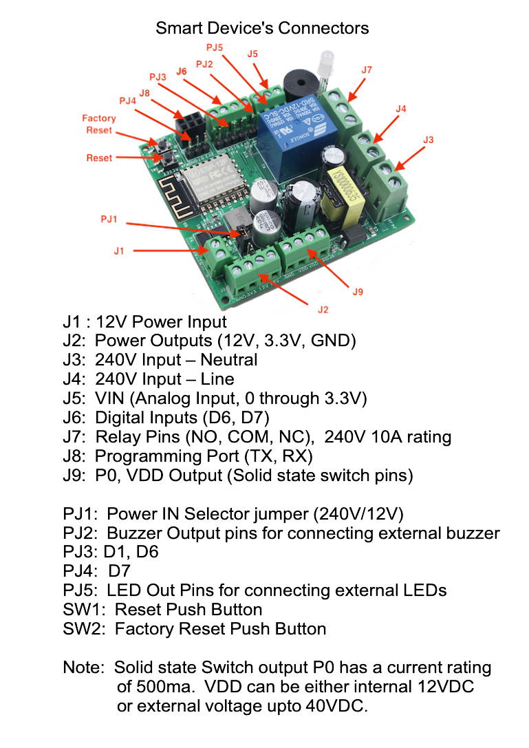
Fig 2: Smart device's Connectors.
All the pins of all the connectors are marked on the PCB of this development board.
This development board can be purchased either from eBay or from Amazon. It will be available through other sources in the future. Search for WifisecureAccess in eBay or Amazon.
2.0 Use the Smart device as an IOT Development Board
For those who are looking for a microcontroller development board, or an IOT development board, this smart device can easily be used. This is ideal for schools and other educational institutions for learning microcontroller programming using Arduino IDE. This board is also very ideal as an IOT development board for those who want to load their own program to control equipments.
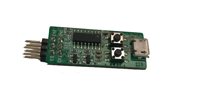
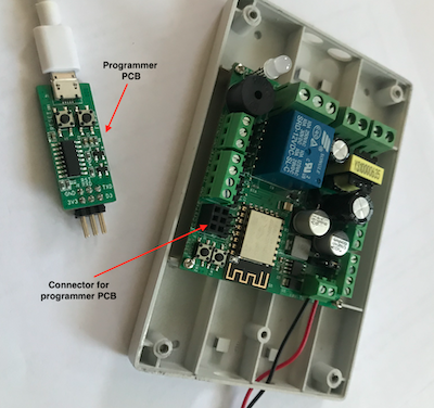
The device can be connected to a USB port on your computer and Arduino IDE can be used for developing programs. In order to connect to a USB board on your computer, you need a serial interface board. Fig 80 shows the serial interface programmer board. This uses a CH340G serial-to-usb chip. This can be purchased from Bhadre by Contacting them. This, along with the smart device, will be available for purchase as a development kit from eBay.
Note: Development board may not come with the firmware of WiFiSecureAccess. So, if you try to install it as per the previous sections of this documentation, it will not work. The development board is for the customers to develop their own programs.
Fig 80: Programmer Board
2.1 Components Required to Program the Device
WiFiSecureAccess development board (to be purchased from eBay or Amazon)
A Computer. It can be a windows machine or Apple macbook
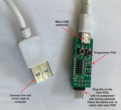
WiFiSecureAccess Programmer PCB (This comes with the WiFisecureAccess development board)
USB cable with one end a micro usb connector and the other end a matching usb connector to the computer
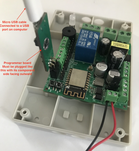
The following figures show the programmer PCB with USB cable.
To program the smart device, you need a computer with Arduino IDE installed. Download Arduino IDE and install it on your computer. Arduino IDE is available free for download. https://www.arduino.cc/en/software
In short, the steps to setting up the computer are:
1) Install Arduino IDE
2) Open Arduino IDE
3) In Arduino IDE, go to File → Preferences (In Mac, Arduino → Preferences).
On that page, add the following in the Additional Boards Manager URL
http://arduino.esp8266.com/stable/package_esp8266com_index.json
4) Click on Tools → Boards → Boards Manager.
Then search for ESP8266 and install the library ESP8266 by ESP8266 Community
5) Next, select the board by clicking on
Tools → Board → ESP8266 boards → NodeMCU 1.0 (ESP-12E Module)
6) Then, click on Tools → Upload speed → 115200
7) Now, plug-in the USB-to-Serial converter board on to the development board. Then cable that to a USB port of your computer using a micro USB cable.
Then power on the development board.
Then click on Tools → Port → select the correct serial port.
Note: You should be seeing a new serial port already for this board. It may be COM3 on Windows, or /dev/cu.wchusbserial1430 on MAC.
If you do not find the serial port, you may have to install the serial driver as per the steps below:
Download the driver from the following location. http://www.wch.cn/download/CH341SER_EXE.html
Or,
https://sparks.gogo.co.nz/ch340.html
And, follow the instructions given in the following document.
https://www.dnatechindia.com/ch340g-drivers-download-installation-guide.html
8) Open serial monitor of the Arduino IDE by clicking the button on the top right corner of Arduino IDE window. If all previous steps have been done correctly, it should open a new terminal. You need to set its baud rate. Check its baud rate at the bottom tab. By default, it may be 9600. Change it to 115200.
Note: The computer will detect the Serial-to-USB adapter only if it is connected tp the device and the device is powered ON. This is because the serial-to-usb adapter takes power from the device and not from the computer.
Now, your computer is all set for developing programs for the development board.
You can now write your own program in Arduino IDE, compile it and load it to the smart device. Keep in mind that WiFiSecureAccess IOT platform and its features described in all the above sections of this document will not be available when you load your own program on to the device.
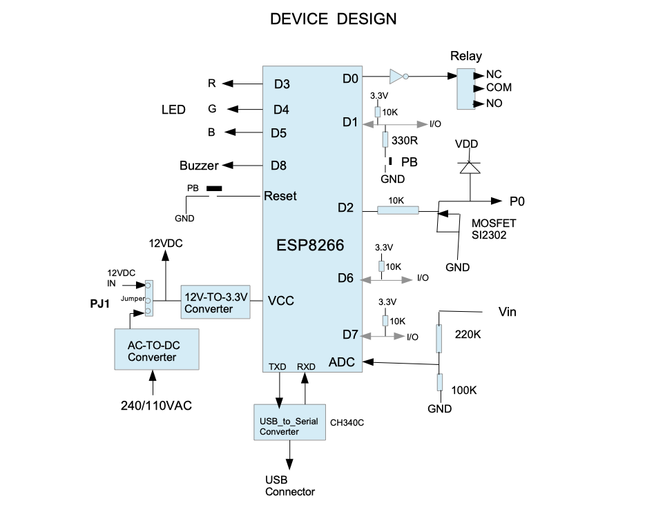
Fig 84 shows the hardware architecture of this device showing all the IO pins. This figure shows what pins of ESP8266 are connected to the buzzere, LEDs, relay, and the solid state switch P0. It also shows the inputs as D6 and D7 of the ESP8266. The diagram also shows the values of the voltage divider used at the analog input of the ESP8266. These informations will be useful when writing programs on your own.
Fig 84: Hardware architecture of the Smart Device
With this setup, the device can be used as an IOT development board. It can also be used by schools and other educational institutions for learning embedded programming as well as microcontroller programming.