Note: This documenation is for hardware version 2.1. This is now deprecated in favour of hardware version 3.x
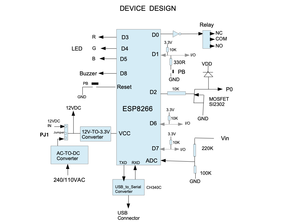
The smart device is an ESP8266 based hardware with a powerful WiFi.
The device has an AC-To-DC power supply onboard.
It can also take a 12V power instead of an AC power.
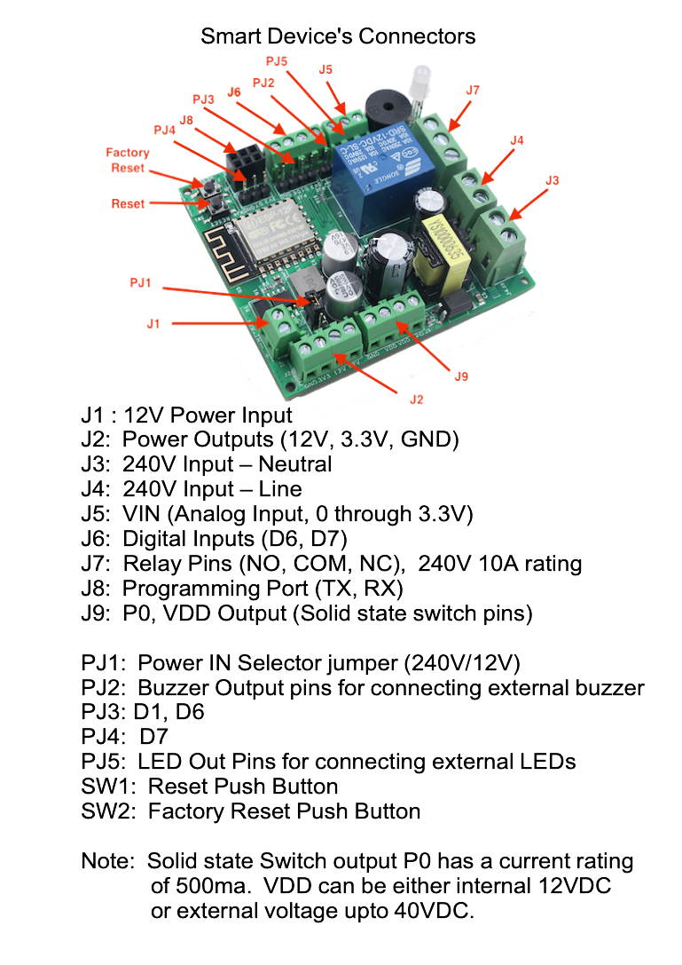
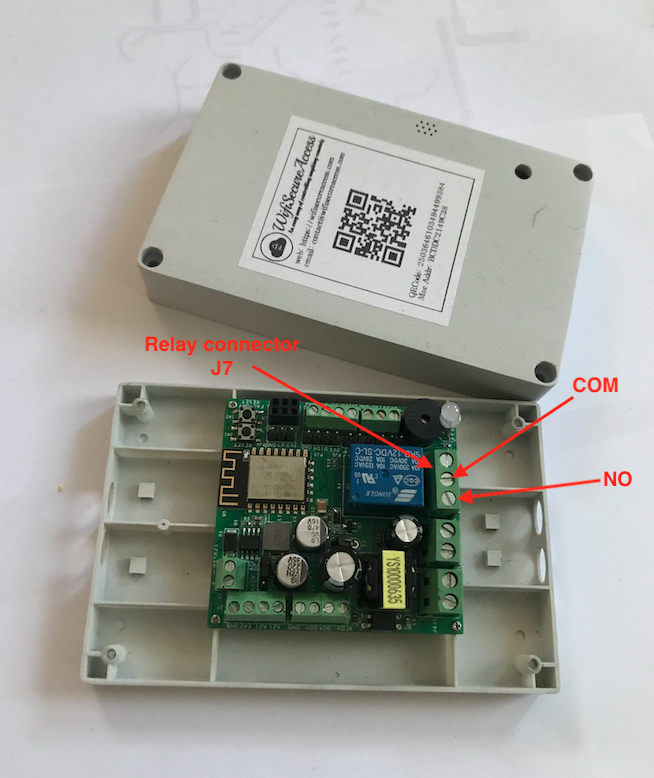
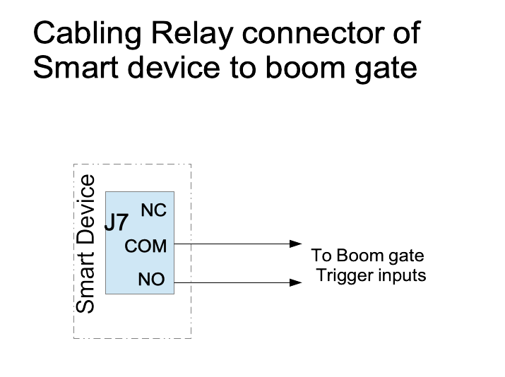
The device has one relay with NO, NC and COM available at its connector.
The relay pins are rated 240VAC/10A. So, it can be used to put ON/OFF AC source as well.
In addition to this, the device has one solid state switch rated at 12V/40V, with a current rating of 500ma.
This can be used to operate any external relays, solenoids or anything similar.
The device also has internally operated Buzzer and LEDs.
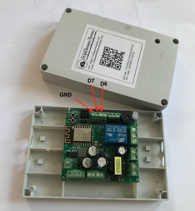
This smart device also has two digital inputs (D6 and D7) and one analog input Vin. D6 and D7 can be used to read any ON/OFF signals such as limit switches, motion sensors and so on. These can also be used to read digital data from temperature/humidity sensors, ultrasound sensors and so on. This smart device is compatible with almost all sensors that are available for Arduino. The analog input Vin can be in the range of 0 through 3.3V. The device also has a Reset button and a Factory-Reset button
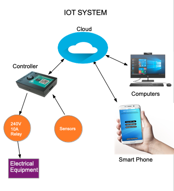
This smart device is a part of our IOT system which has an architecture as shown in Fig.3.
The device comes with a firmware pre-programmed. Firmware can be updated online.
To use this smart device to monitor sensors, and/or to activate equipments and external devices, no programming is required.
Everything can be done by configuring on our web interfaces.
Our IOT system comes with an app for smart phones.
The ports of these smart devices can be activated either by scanning its QR Code/NFC Tag or by pressing a button on the smart phone or using Google Home Assistant or Amazon Alexa.
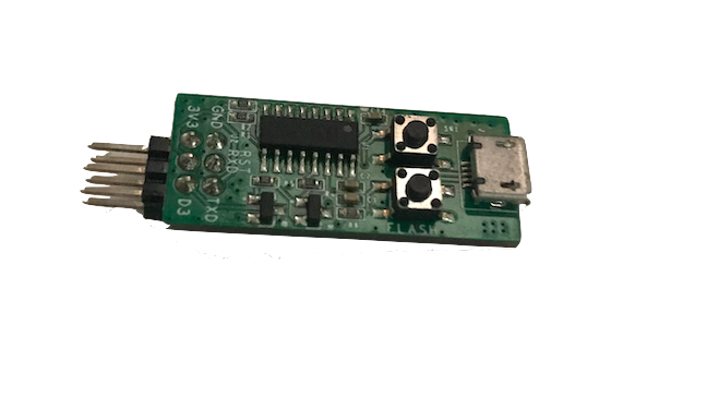
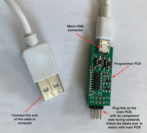
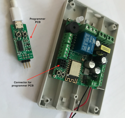
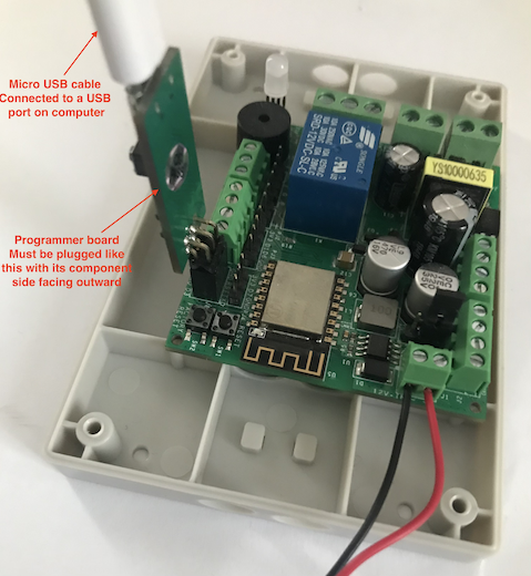
And, for those hobby enthusiasts who want to write their own program without using our IOT system, we provide a programmer board that can be used to connect this to the USB port of a computer.
Arduino IDE can, then, be used to program this.
(Note: We do not recommend this for normal users as it is not required for normal users of our IOT system).
Fig 3: IOT Device Architecture.
2.0 Installation
This smart device can be purchased either from eBay or from Amazon. It will be available through other sources in the future. Search for WifisecureAccess in eBay or Amazon.
Note: If you have purchased a dedicated garage door controller (hardware version 0), instead of seeing this documentaion, click here to see its detailed documentation.
Once you receive the device, you need to execute the steps described in this section of the documentation to set its WiFi and take its ownership and to configure for use.
2.1 Setting up the App on your Smart Phone
If you have not downloaded the wifisecureaccess app yet, please download it to your smartphone now.
Search for wifisecureaccess in either Apple Store or Google Play store.
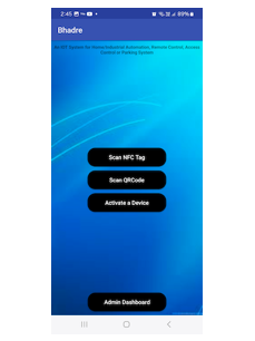
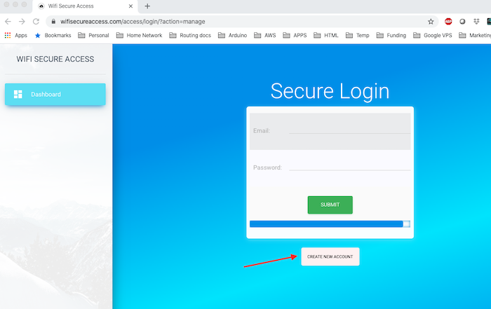
Once downloaded, open the app and press Admin Dashboard. It will prompt you to enter your username and password to login.
If you have not registered yet with https://wifisecureaccess.com, press 'Create NEW Account' button on this page and register.
Fig 3A: App's opening page
Fig 3B: Login Page
Fig 3C: Register (Create a new account)
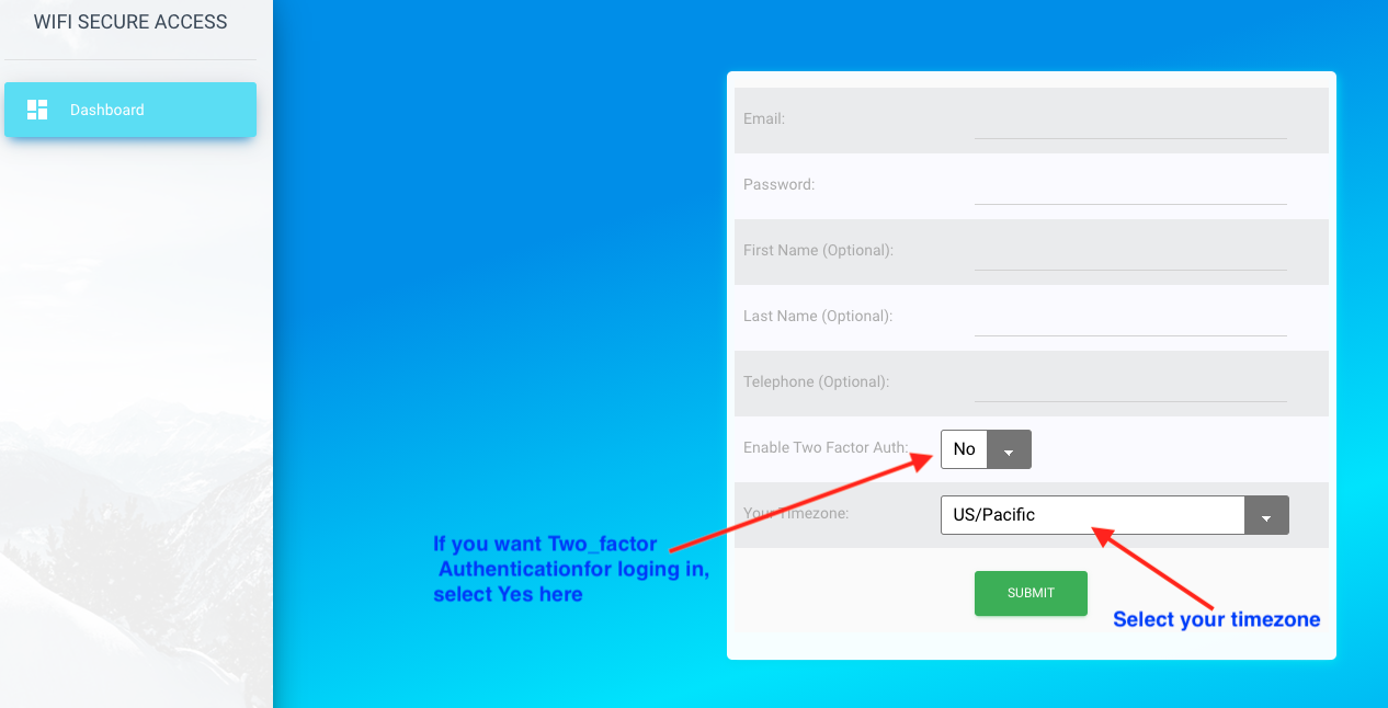
Follow the prompts and instructions. It needs your email address and telephone number as well as a password. Telephone number is optional.
Password must have at least 8 characters (maximum 20 characters) and it must contain at least one lower case letter, one upper case letter, one numeric. The system will prompt you for your email verification.
The system uses email address as your username.
It also uses it to send notifications of events in the device, if you have configured the device to send you notifications.
The other two fields "Enable Two Factor Auth' and 'Timezone' will be defaulted to 'No' and 'US/Pacific' respectively. You can enable Two Factor Authentication by selecting 'Yes' for this field, if you want to. When selected 'Yes', a confirmation code will be sent to your email whenever you try to login. This is an additional layer of security for your account. The timezone is your timezone. Select it from the pull-down menu. The default is US/Pacific. Setting this to your timezone will help the system display the times of all your activity in your local time. All these parameters can be changed any time later by clicking 'My Profile' under 'User Admin" in the Dashboard.
Please keep your password confidential to make sure that the device is used by authorised persons only.
Note: The steps of setting up the device and configuring it can be done either using a smart phone or using a computer.
On a computer, you can open a browser and go to https://wifisecureaccess.com/access/index. It will prompt you to log in.
On a smartphone, open the wifisecureaccess app and press on Admin Dashboard in the main scanning page to get to the dashboard.
We recommend that you use a computer for all initial setup and configurations.
However, use your smart phone when you want to activate a device or its ports from remote, or when you need to scan its QR Code or NFC Tag, or when you want to use Google home assistant or Amazon Alexa.
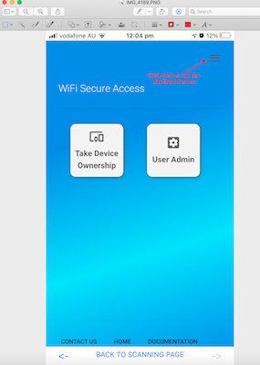
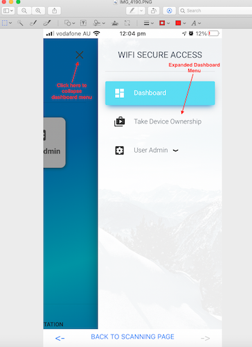
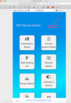
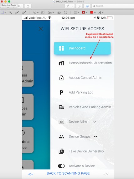
If you are using a smart phone to register, you will see a page similar to Fig 3D. Or, any time in the future, if you open the app and click on the Admin Dashboard, the same display will be shown. You will notice that all the admin menu is collapsed. To see the admin menu, click on the three lines at the top right corner of this page as shown in Fig 3D and 3E.
Fig 3D: Dashboard Menu on Smartphone (collapsed)
Fig 3E: Dashboard Menu on Smast Phone
2.2 Setting up the Device
Once you have purchased a device, you need to power it on, assign its ownership and set its WiFi, as an initial setup as per the steps described here.
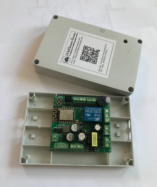
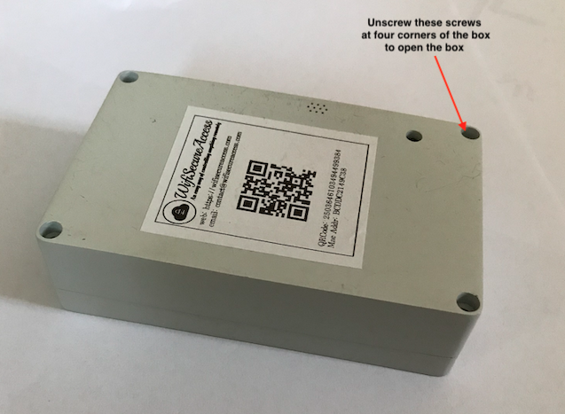
The device comes to you with its PCB mounted inside its plastic casing. To connect power to it, or to connect anything to this device, you need to open the box and connect cables to the appropriate connectors.
Begin the installation process by connecting power to the device,
so open the box by unscrewing the four mounting screws as shown in Fig 4.
Fig 4: Device's Casing.
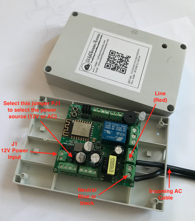
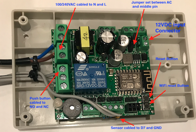
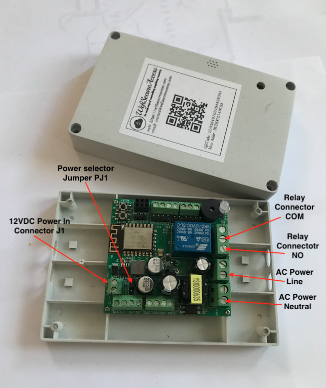
Fig 5: Connecting Power to the Device.
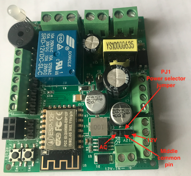
Fig 5A: Power Selector Jumper PJ1.
Warning: If you are using AC Power, it is important to take care as 110V/240V can cause harm, unless handled properly. If you are not knowledgeable enough to handle AC power, we recommend that qualified electricians are engaged to do cabling of AC power lines. WiFiSecureAccess takes no responsibility for any harm caused due to mishandling of this device with AC power by unqualified personnel.
If you are using 12V power, connect 12V to connector J1. Make sure that positive is connected to positive and ground to GND of that connector J1.
If you are using AC power (110V or 240V), connect phase (Line) to any one of the two terminals of J4, and neutral to any one of the two terminals of J3.
Note that connectors J3 and J4 have two terminals each. Do not accidentally connect Line and Neutral to the same connector. Take precautions.
See the correct cabling in the Fig 5 shown above.
After connecting the power, you need to select the power source by using the jumper PJ1.
If you have connected AC power, set PJ1 to AC by putting the jumper between the middle pin and the pin marked AC. If you are using 12V power, set PJ1 to 12V by putting jumper between the middle pin and the pin marked 12V. Then, put the power on at the wall switch.
If power cabling is correct, you will notice that the LED either blinks Blue or stays at Blue. This indicates that it is trying to connect to WiFi. It will stay in that state until it connects to WiFi.
CAUTION: If you are using AC power source for this device, all cabling must be done by a qualified electrician, as AC has safety concerns. Once AC power is connected to this device, one has to be careful in touching this device as the connectors J3 and J4 as well as AC lines on the PCB can cause electric shock when touched. WiFiSecureAccess takes no responsibility for any harm caused due to mishandling of this device with AC power by unqualified personnel. This device is not a DIY when it comes to using AC power.
2.3 Setting WiFi of the Device
There are two ways of setting the WiFi of the device
Using the hotspot of your smart phone
Setting the device as a web server and using a browser (Chrome preferred) on your computer or smart phone. Refer to Section 2.6 of this documentation for this method.
Using the HotSpot on your smart phone
If this is a brand new device, its WiFi has been factory reset to the following:
Upon factory reset, the device listens on a WiFi (2.4G) with the following ssid and password:
SSID : MyPhone Password: 12345678
So, when the device is powered ON, it is trying to join this WiFi. Therefore, in order to initially connect to WiFi, you need to setup a mobile hotspot on your smart phone temporarily to this SSID and password so that the device gets connected to internet which will enable you to change its WiFi. Note: (The device is not capable of 5G and so, WiFi must be 2.4G.)
If you are using iPhone, change its Personal hotspot WiFi settings to match the above and put Personal hotspot ON. To change your iphone's SSID, you need to change the name of your phone to MyPhone. This can be done in settings → General → About → Name. To change password, Settings → Personal Hotspot → Wi_Fi Password. Once changed, click on Allow Others to Join so that your Personal Hotspot is ON with this SSID and password.
If you are using an android phone, go to settings → Tethering and Mobile hotspot. Then click Mobile hotspot. Then click on the three dots at the top right and click 'Configure hotspot'. Then change the ssid and password of your mobile hotsopt to 'MyPhone' and '12345678'. Note: If your smartphone is capable of 5G hotspot as well as 2.4G, make sure that 2.4G is selected as the device is not capable of 5G. Also, check the Timeout settings of the hotspot. Set it such that it does not timeout too soon while you are using Hotspot. You can set it to Never time-out. After setting it, switch on your mobile hotspot (in the previous menu).
Note: Make sure that the mobile data on your smartphone is turned ON so that the device connected to your hotspot can get access to internet. Also, make sure that the Hotspot stays ON and never times out until you change the WiFi of the device as per the steps in Section 2.5. Your mobile phone must not go into a sleep mode until you change the wifi of your device. For this initial setup, it is important that the device gets connection to internet through the hotspot on your smartphone. If the LED stays flashing blue, that means that it is unable to join the WiFi. If you observe the LED flashes blue with occasional flashing RED, it means that it is unable to connect to the internet after joining WiFi.
Once the personal Hotspot is ON, put on the device, if it is not already ON. You will notice that the device will join that WiFi and connect to internet. You will see in a few seconds that the LED changes colour to RED, and staying RED. If that is not happening, make sure that your personal Hotspot is configured correctly and that it is ON. If this is not happening, there is a problem with the WiFi. You can do a factory reset of the device as explained in section 2.6 of this documentation and try again. If the device is still not joining WiFi, ask for help by contacting contact@wifisecureaccess.com.
If the device is connected to WiFi and conected to internet, the LED will stay steady RED. Then, you need to take the ownership of this device as explained in section 2.4 below before you can set its WiFi.
2.4 Taking Ownership of the Device
There are two ways in which you can take the ownership of a new device that you just bought. One method is by scanning the QRCode of the device using your smartphone, and the other method is by using a browser on a computer. Before you proceed, make sure that you have turned on the device and it has joined the WiFi of the Hotspot of your smart phone, as explained in the previous section of this documentation.
In the first method. open wifisecureaccess app on your smartphone and go to Scanning page and press Scan QRCode button.
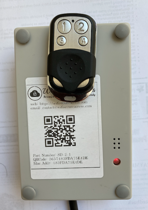
The camera will come ON. Scan the QR code of the device. The QRCode is on the label pasted on the box.
Then follow the prompt. You will be prompted to confirm the buzzer sound as well as the color of the LED a few times to make sure that you have this device in front of you, having connected to internet. If everything is correct, it will assign the ownership of this newly bought device to yourself.
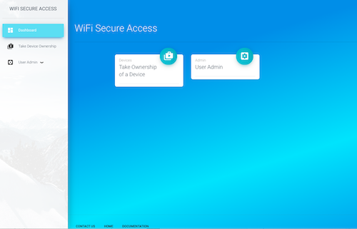
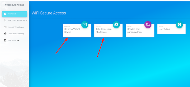
For the second method, open https://wifisecureaccess.com and click on Dashboard. If you are already logged in, you can see a tab "Take Device Ownership" in the sidebar menu. If this is your first device, you will see that on the main page as well. Click on that, and follow the prompt. After getting the confirmation that the device is turned on and connected to internet through its WiFi, you will be prompted to enter the QRCode or Mac address of the device. On the label of the device, you will see either the mac address or the QRcode of the device. Enter it as shown on the label. Follow the rest of the prompts. If you respond to all the prompts correctly, the ownership of the device will be assigned to you and a popup window will appear confirming it.
Fig 6: Intial page view.
Once you have taken ownership of the device, your main dashboard page may look like the one shown in Fig 6A. And, if you expand the dashboard menu, you may see several otions as shown in Fig 6B.
Fig 6A: Dashboard view when you own a device
Fig 6B:Dashboard expanded menu when you own a device
Once the ownership is transferred, click on
Home/industrial Automation Dashboard menu. Then click on My Devices in Automation.
You will see your device listed there. If you have more than one device, all of them will be listed there. Once the device is assigned to you, nobody other than you will be able to configure it. In the later sections of this documentation, you will learn how to allow others to use this device. You will also learn how to configure this for your specific needs and how to use it.
2.5 Changing WiFi of the Device
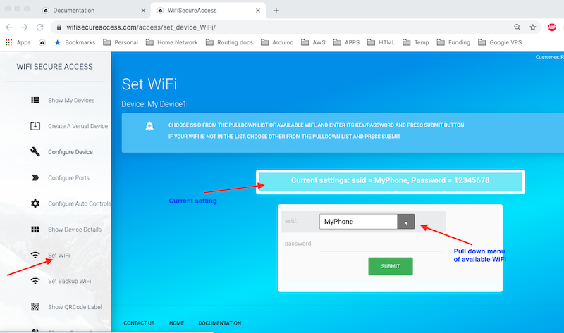
If the device is already connected to internet, you can change its WiFi any time as per the steps given here. In the dashboard menu, click on 'Devices Admin' to expand that menu. Then click on 'Set WiFi'. It will take you to a page where it will prompt you to enter the SSID and password of your WiFi. Make sure that the WiFi is 2.4G and not 5G. The device is not capable of 5G WiFi. If the device is running firmware versdion greater than 4.1, you will see a pulldown menu with all the available WiFi at that location. You can choose one, or select 'Other...' to enter any other ssid. Once entered, click Submit. If successful, you will see the device restarting, the led blinks blue and then changes to steady Red. The device is now set to go and ready for use.
Note: The new WiFi must have access to internet. Not only that it is able to connect to WiFi, but it also needs access to internet. In other words, the router of your WiFi must have connection to internet for the device to accept this ssid and password that you entered.
Note: If the LED keeps flashing Blue and stays in that loop, that menas that it is unable to connect to WiFi. There is something wrong with the ssid and password that you set. If you observe LED flashing Blue with occasiuonal flashing RED, that means that it is able to connect to WiFi, but it is unable to connect to internet. That can happen if your WiFi has no internet access.
If you accidentally entered wrong ssid or password, or if the device is not getting connected to the new WiFi, you will hear double beep from the device, if the device is running firmware version 4.1 or above. It will then revert back to the previous ssid and restart. If it is unsuccessful to connect to previous ssid, it will stay in that loop of attempting to connect, and LED will keep flashing. If the device is running older versions of the firmware, you have to do a factory reset as per the steps given in section 2.6 of this documentation, if it has failed to connect to the new WiFi.
Fig 8: Setting WiFi of the Device.
The device will remember the WiFi that you set and will connect to that WiFi hereafter whenever power cycled or reset.
If you have used mobile hotspot of your smartphone to get initial connection, you can switch that off now. You can change your smart phone's name and WiFi password to whatever they were initially.
After switching off the hotspot on your mobile phone, try resetting the device by pressing the reset button on the device.
If everything is set correctly, the device will restart and connect to the WiFi.
You will see LED blinking Blue while trying to join WiFi and then turning to red when successfully connected to WiFi and connected to internet and the cloud server.
If this is not happening, there is something wrong either with the ssid and password that you entered, or with your internet connection through WiFi. Make sure that the ssid and password that you set are that of a 2.4G wifi and not 5G. Make sure that your router has internet connection.
If anything has gone wrong, do a factory reset of WiFi as per the steps in section 2.6 of this documentation, and then try to set WiFi again.
2.6 Doing a Factory Reset of WiFi
The WiFi of this device can be reset to the factory reset any time, if you find a need for it. The factory reset WiFi is : ssid = MyPhone and password = 12345678.
If the device is running firmware version 4.2 and above, you can also set its WiFi using a browser on your computer or Smart Phone by doing a factory reset. This is another method of setting WiFi of the device. After doing a factory reset, follow the steps given here in this section to do so.
To do a factory reset, open the box of the device, and locate two push buttons marked Reset(SW1) and Facory Reset(SW2). Factory Reset Button is also called WiFi reset button. Refer to Fig 8A below to locate these push buttons. If the device is operating at 110V/240VAC, make sure not to touch any of the high voltage tracks or terminals to avoid getting shock. Then, press and hold SW2 (Factory Reset button). While holding it, press and release SW1 (Reset button). Keep holding Factory Reset button until the device restarts and LED changes to flashing blue/green. Then, LED will change to BLUE. At this moment, the ssid and password of the device has been reset to 'MyPhone' and '12345678' respectively. You can release holding the factory reset push button.
Fig 8A: Factory Reset Push button on the device.
If the device is running firmware version below 4.2, it will attempt to connect to wifi swith SSID = MyPhone and password = 12345678. This is the method that we discussed in section 2.3 earlier in this documentation. You will see LED Blue and flashing occasionally. If you have enabled hotspot on your smartphone, the device will connect to it. and the LED will turn solid RED. If it is unable to connect, LED will flash blue occasionally and stay in that loop until connected. Refer to Section 2.3 of this documentaion, and then follow section 2.4 to take ownership of the device and section 2.5 to change its wifi.
When the device is running firmware version 4.2 and above, the device will go into an access point mode and operate as a web server. It will advertise an SSID = WiFiSecureAccess. LED will stay solid BLUE without any occasional blinking. Follow the steps below to set its wifi at this time. (Note: If you press reset push button again at this time, the device will change to the previopus mode and will attempt to connect to factory reset ssid)
Setting WiFi of the device using a browser when the device is is web server mode
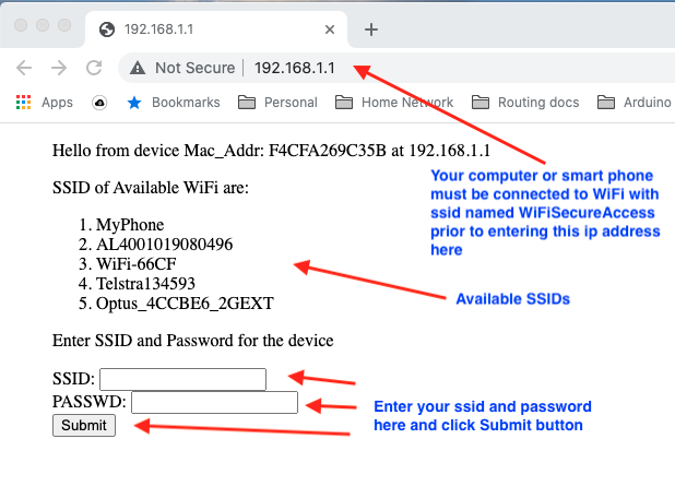
If your device is running firmware version 4.2 and above, factory reset will put the device in web server mode advertising an SSID = WiFiSecureAccess, and LED will stay solid BLUE without any occasional flashing. If you look at the available WiFi in your smart phone or computer, you will see this WiFiSecureAccess there. You will see this only after doing a factory reset of the device that is running firmware version 4.2 and above. Now, connect your computer or smart phone to this WiFi. Once your computer or smartphone is connected to this WiFi, open a browser (Chrome preferred) on your computer or smart phone and enter the ip address 192.168.1.1 in the url. You will see a window similar to the one shown in Fig 8B below.
Fig 8B: Setting WiFi using a browser.
On this page, it will list all the available SSIDs. Enter your SSID and Password and press Submit button. If your entry is correct, the device will set the WiFi of your device to that. Then it will try to connect to that wifi. You will see LED flashing BLUE. If it is able to connect to this wifi, you will see the LED changing to RED and staying RED (solid RED). If this is a brand new device, as a next step, you need to assign the ownership of this device as explained in section 2.4 of this documentation. If ownership is already assigned, the device is ready to be used.
If it is unable to connect, the device will beep twice (after a few seconds of attemtps) and will revert back to the factory reset ssid (MyPhone). Then, it will try to connect to factory reset ssid. If so, follow the steps as explained in section 2.3, or do the factory reset again and enter the correct ssid and password.
Note: If the LED keeps flashing Blue and stays in that loop, that menas that it is unable to connect to WiFi. There is something wrong with the ssid and password that you set. If you observe LED flashing Blue with occasiuonal flashing RED, that means that it is able to connect to WiFi, but it is unable to connect to internet. That can happen if your WiFi has no internet access.
2.6A Setting a backup WiFi
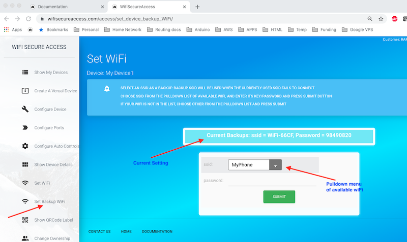
If the device is running firmware version 4.2 and above, and if you have more than one WiFi at your premises, you can set up a backup WiFi on this device so that the device will switch over to the backup WiFi whenever the main wiFi fails. Unless you set a backup WiFi, the default backup wiFi is the main WiFi that you have set. If you want to set a backup WiFi, open the dashboard and click on 'Set Backup WiFi' under Device Admin. You will see a page similat to Fig 8C. Just like the way you set the main WiFi in section 2.5, this page shows all the available WiFi in a pull down menu. You can select one of those, or select 'Other ...' to set anything else. Once selected, press Submit.
If successful, the device saves this backup WiFi and will switch to this WiFi whenever the main WiFi fails with three attempts.
Fig 8C: Setting Backup WiFi
Note: If any time need arises, you can use your smartphone's hotspot as a WiFi connection to the device. If you do a factory reset (we called this 'WiFi Reset' a few times), the device resets its WiFi to ssid = MyPhone and password=12345678. If you set the hotpot's ssid and password to this and enable hotspot on your phone, the device gets connected to internet. This feature becomes handy when all the configured WiFi fails.
2.7 Initial Minimum Configuration of the Device
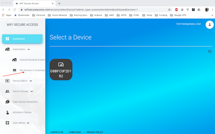
Once the above steps are completed, click on Home/industrial Automation in the dashboard menu. Then click on My Devices in Automation. You will see this device listed there with its name as its mac address. If you have more than one device, all will be listed here.
Fig 9: Devices List.
PS: If this device is in Access Mode, the output port which is in access mode may not show the current status (Open/Closed) exactly unless a sensor is installed and at least one notification is enabled. Refer to section 6 of this documentation.
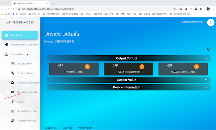
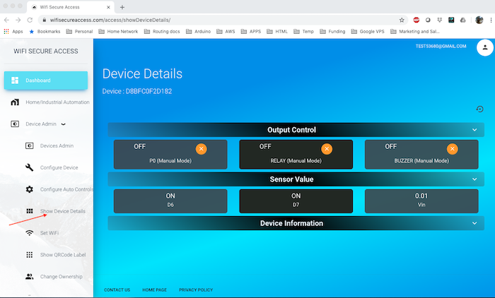
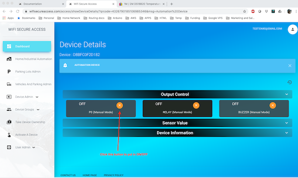
Click on any device. It will show the details of that device. You will see its three output ports (P0, RELAY and BUZZER). It will show whether the output ports are currently ON or OFF. If it is ON, you will see a green circle with a check mark. If it is OFF, you will see an orange circle with a cross mark. You can toggle its state by clicking that circle. This, thus, shows how you can put a port ON/OFF from remote without doing any additional configurations.
Fig 10: Device Details.
Now, click on Sensor Value on this page. You will see three sensors listed here: D6, D7 and Vin.
You will also see the current values sensed by these inputs. D6 and D7 are initially ON/OFF inputs.
If you apply a 0 volts at the connectors of D6 or D7, you will see this display as OFF (reverse logic) , and if you connect 3.3V (or, if nothing is connected), you will see it displaying ON.
In the later sections of this document, we will describe how special sensors such as temperature, humidity, ultrasound and so on can be connected to these.
Fig 11: Device Details.
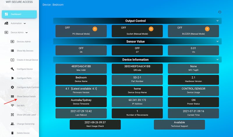
Now, click on Device information. It will display all the details of this device such as its mac address, QRCode, NFC TagID, name of the device, firmware version, device owner and so on. On the firmware build as well as firmware version tabs, it will show you the current version and the latest version available. If the firmware is not up to date, you will see an orange button to click on to update its firmware.
Checking and Updating Device Firmware
To check the current firmware and to update its firmware, you can revisit this page (Fig 12) by clicking Device Details under Device Admin. Then click on Device Information to see the full information of the device. The Firmware version tab on this page will show the current version of the firmware on your device as well as the latest available. If the latest version or latest build is higher than the current build and current version, you will see an orange button on that tab. Click on that button to update its firmware.
We Strongly recommend updating the firmware to the latest by clicking the link on this page, if it shows new firmware is available
Fig 12: Device Details.
There are several parameters of the device that are displayed in the Device Information (Fig 12). These are all for information. You mau have a close look at all of them. Number of reconnects in this is the number of times the device lost connection to the server since the last reboot. If you see a higher number here, that indicates a weak wifi, or some frequent issues in connecting to internet.
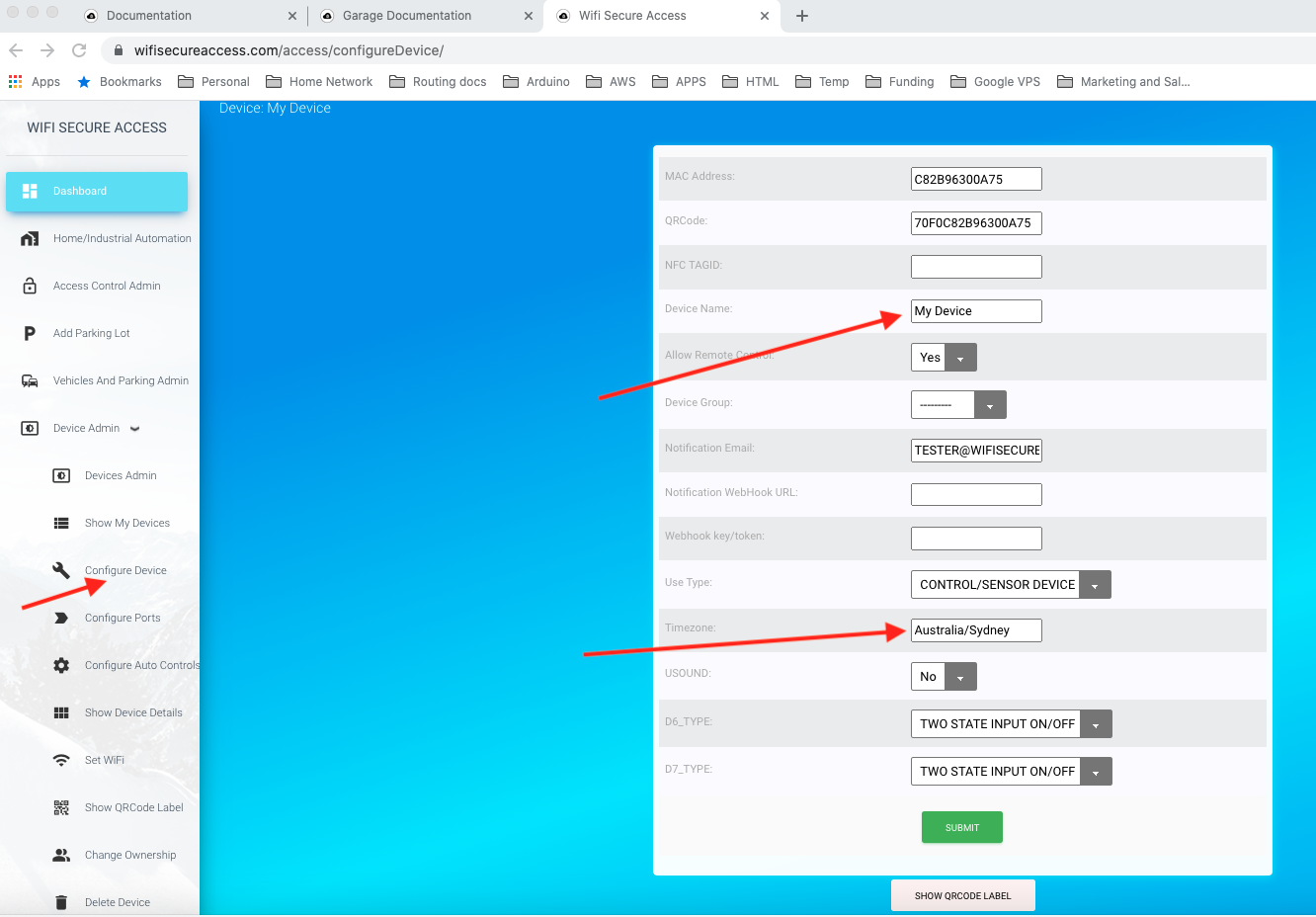
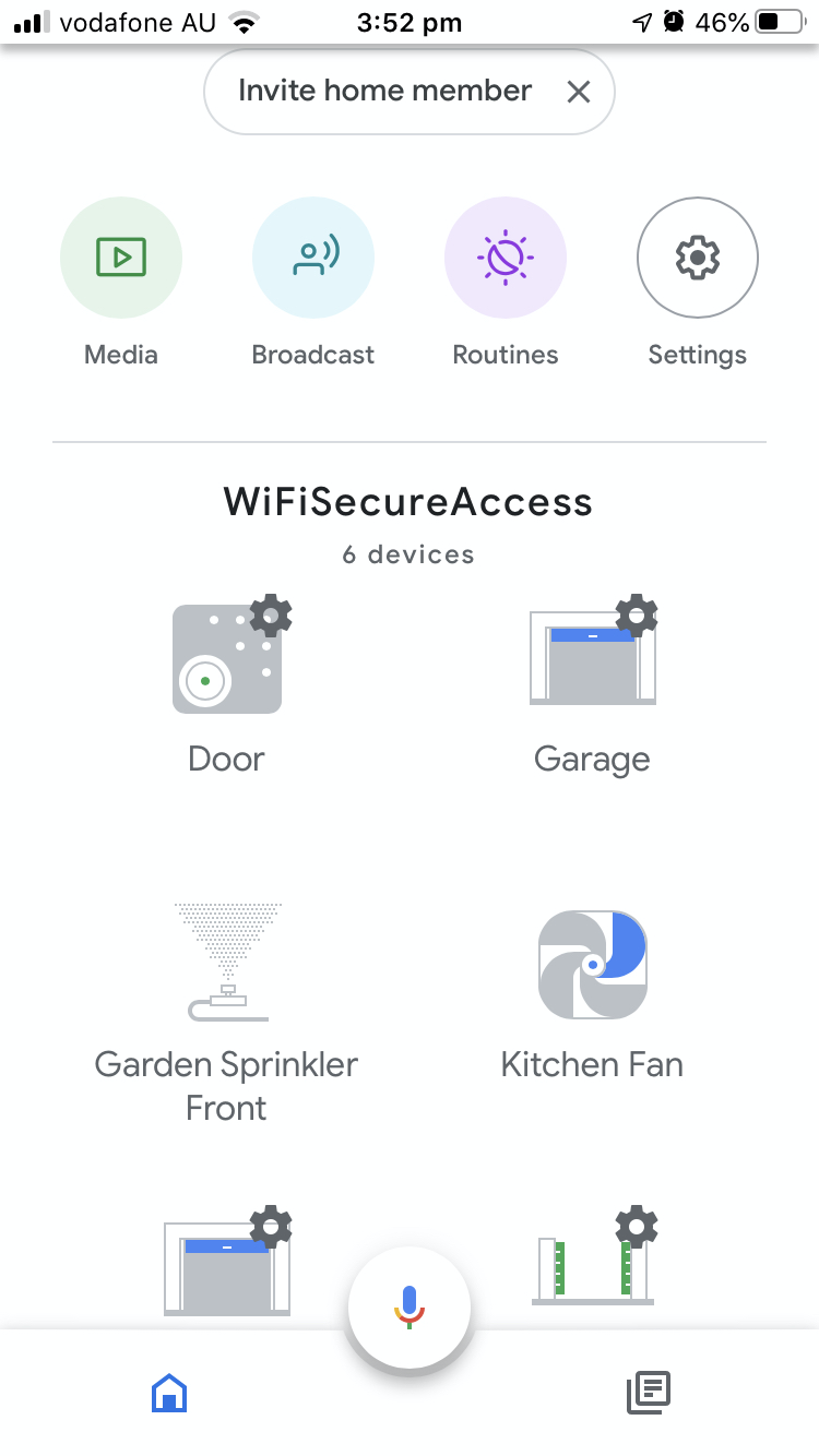
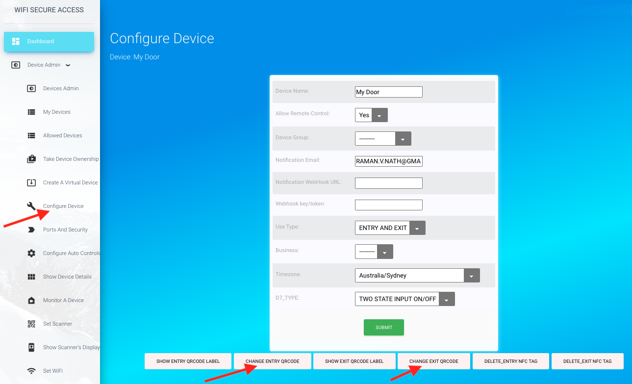
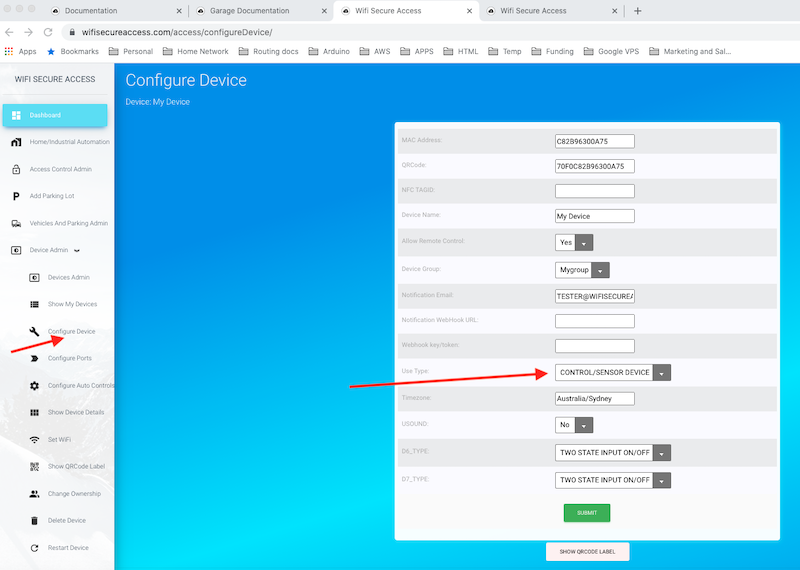
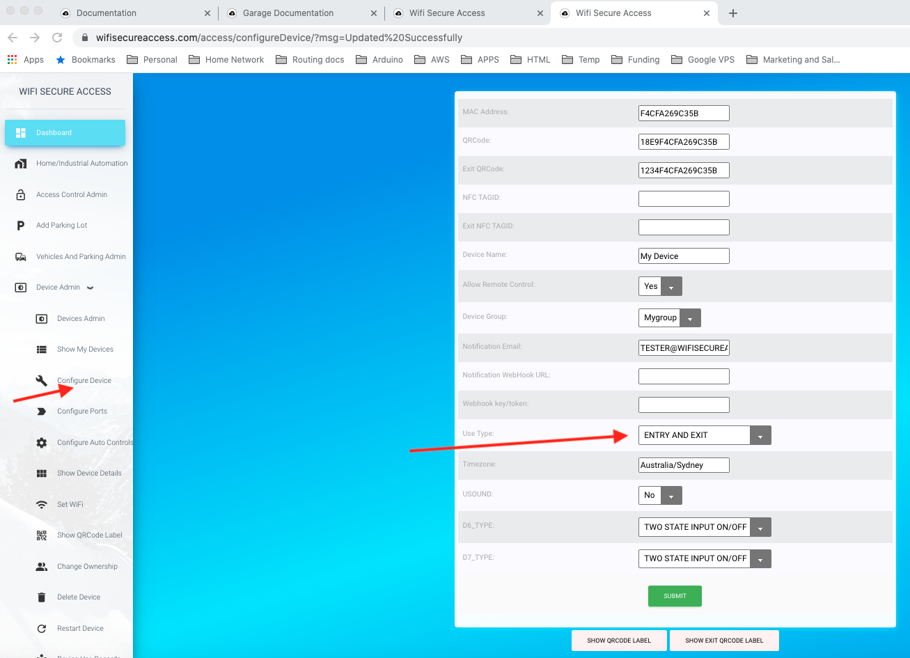
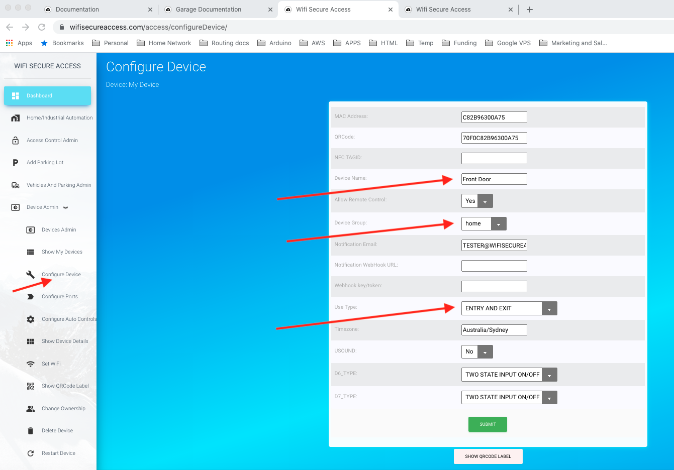
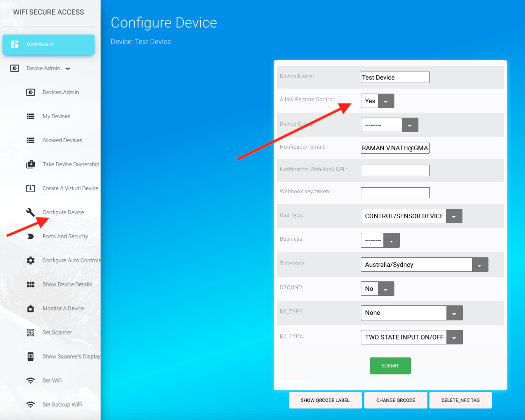
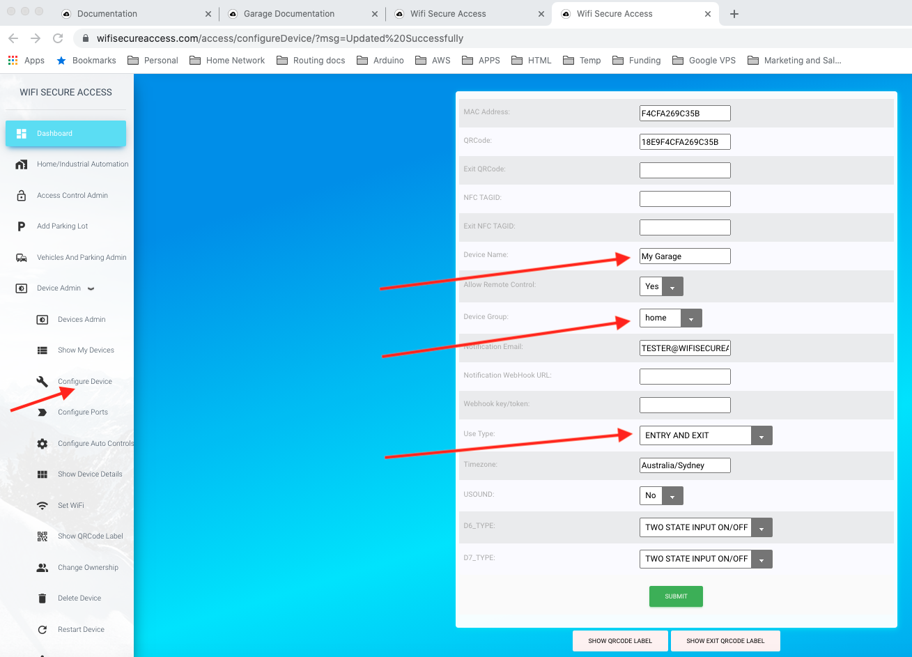
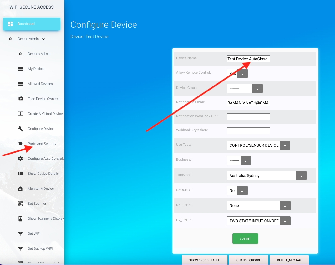
You can change the name of the device as well as the labels of each port, if you prefer. To change the name of the device, click on 'Configure Device' under Device Admin on the left side bar menu. It will present
a form similar to Fig 13. If you are using this for access control, add the word 'Door', 'Gate', 'Garage', 'Lock', or 'Parking' in the name depending on where this is used. You will learn later in Secion 6 that this will help the device autoconfigure itself for Door, Gate or Garage. Otherwise, you can Change the name of the device to anything you like and click Submit.
We recommend that you also change the timezone to the time zone where the device will be installed. By default, it is UTC. Click here to know the format of different time zones.
Unless you change it to your timezone, all dates and times will be displayed in UTC.
Fig 13: Configure Device.
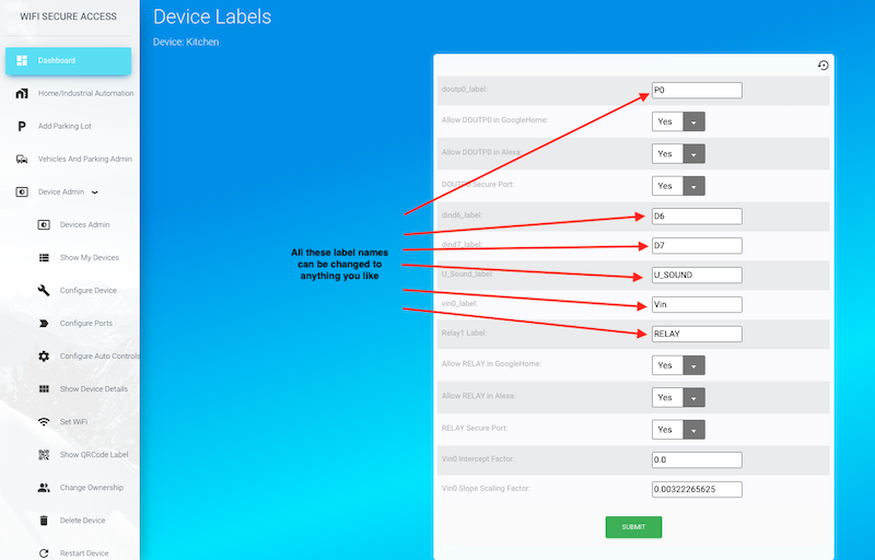
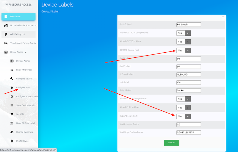
The names of the ports are also changeable by clicking on 'Ports and security' under 'Device Admin' in the Dashboard menu. Fig 14 is the form that will show up when clicking 'Ports and Security".
Note: We recommend not changing these labels now. You can do this later when you start using these ports for controlling external devices such as 'Door', 'Garage' etc.
Fig 14: Device Labels.
Note: The names that you assign to a device and its ports have some special significance. If the names contain words such as 'Door', 'Gate', 'Garage', 'Lock' and 'Parking', the mode of operation will automatically get changed to Entry/exit type. It is assumed that you are using this to control entry/exit of a door, garage, gate or a parking gate, or you are using it to control a lock. This is called "Access Control' mode of operation. In addition, if you add the word Garage, Gate or Parking, it is assumed that smart device is cabled to a controller on those garage/gate/parkibg that needs only a pulse to open/close. On the other hand, if it is a Door or a Lock, it is assumed that the smart device is cabled to an actuator on the Door/Lock which needs a steady voltage acroos it to open as well as to keep it open. Removing that voltage will close it. You can see further details of configuring devices in access control in section 6.0 of this documentation.
2.8 Activating a port using WiFisecureAccess app on the smart Phone
Once the device is installed and ports are configured, you can activate the ports in one of several ways: 1) Using the wifisecureaccess app on the smartphone, 2) by scanning the QRCode or NFC tag of the device, 3) Using Google Home assistant on your smart phone, 4) Using Amazon Alexa, or 5) Making an HTTPS POST call from any of your other applications or programs. In the following sections of this document, you will learn how to use all these different methods.
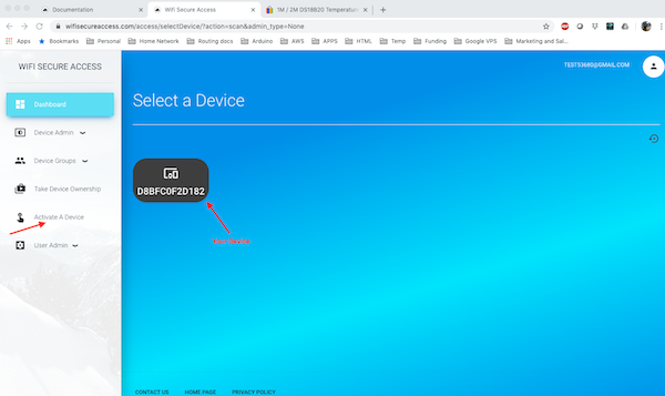
To activate a port using the wifisecureaccess app, download the app on to your smart phone. Search for WiFiSecureAccess app in Google Play store or Apple Store. Once downloaded, open the app and press "activate a Device" button in the home screen. That will display all the devices owned by you (similar to Fig 9). Press the icon corresponding to the device you want to activate. If the device has been configured to operate a door, garage, or gate or a lock, it will activate that immediately. In the later sections of this document, you will learn more about the various types of configurations of a device. If the device is configured for Automation and Controls, it will open up a page similar to Fig 10. Then, you can press the port name to activate any port of that device. Any click on these buttons toggles the state of that port. If it is currently ON, pressing the button will put that port OFF. And, if it is currently OFF, pressing the button will put that port ON.
Note: As mentioned earlier in this documentation, everything that can be done by the wifisecureaccess app on a smartphone can also be done using a browser on a computer, except scanning QRCodes and NFC tags. So, you can activate a port from a browser by opening the https://wifisecureaccess.com and pressing Dashboard. On that page, you will see a link "Activate a Device". When you click that link, it will take you to the same page that you saw on the smartphone listing all your devices. So, by pressing the name of the device, you can activate the device from a browser.
2.9 Activating a port by scanning either QRCode or NFC tag of the Device
As you know by now, by default, each device has been assigned a unique QRCode, and is pasted on the box of the device. You can also view and print its QRCode at any time by pressing Device Admin → Show QRCode Label in the dashboard menu. You can also change the QRCode of any of your devices in the 'Configure Device' menu (Fig 13). You can also delete the QRCode, if you do not want to use QRCode.
To activate a port of a device using QRCode, you can scan this device using wifisecureaccess app. Open the app, go to the scanning page and press Scan QRCode. The camera will become active, and now scan this QRCode. That will take you to the same page similar to Fig 9. There, press the name of the device to activate that device/port. If you are using this device for access control, scanning the QRCode or NFC tag will activate that device (More about access control will be seen on section 6 of this documentation).
It is also possible to assign a unique NFC tag to a device.
If you find a need to use NFC tags instead of QR codes, you can do so by purchasing NFC tags and associating it with the device. We support only Mifare Ultralight 14443-3A type of tags which has 7 bytes of UID. These are very inexpensive tags that you can buy from anywhere. These tags come as stickers as well. Given below is an example link to buy from Amazon. This is just an example. If this link is not available, or if you would like to use a different type, search for a similar item in ebay or Amazon. These NFC tags are available in different type of shapes and packaging. You can use the type you like so long as it is Mifare Ultralite with 7 bytes of UID.
To associate an NFC Tag with your smart device, open the app and press 'Scan NFC Tag' and scan the tag that you purchased.
If this is a new tag and if it is not associated with any other device within our system, you will be taken to a page prompting you to select one of your devices to associate this tag to. The pulldown list will contain all the devices you own (all those devices that are powered on). iIf you have only one device with garage door, you will see only that in the pulldown menu. Select the device that yiou want to associate this NFC tag to. Next, if this device is used in access control, and if this is used for entry as well as exit, yoiu will see another option 'Exit Tag'. Choose 'Yes' if you want associate this with Exit tag, or choose 'No' if you want to associate it with the main entry tag.
Press Submit button after completing the selection.
If entry is correct, this tag is now associated with this device. Now, if you scan it again, it will take you to the Device details page (Fig 10), if this device is in Automation mode; or will activate the port if the device is configured for Door, Garage Door and so on.
You can fix the NFC Tag and/or the QRCode label at any convenient place to access this device. When you use this device for access control of a door, for example, you may want to fix this tag or QRCode label on the outside of the door.
Note: In our IOT system, QRCode as well as NFC Tags are both secure and both do the same job.
Even though anybody can scan these NFC tags or QR codes, only the owner of the device as well as those who are allowed by the owner can access/activate the device. For additional layer of security, you can also enable Two Factor Authentication(2FA) as explained in subsection 2.12 in this documentation. NFC tags are safer than QRCodes as NFC tags cannot be copied (we are using UID of the tag). And, if you do not want anybody to operate this device from remote, you can set "Allow remote Control" (Fig 13) to 'N'.
2.10 Using Google Home assistant to activate a port of your device
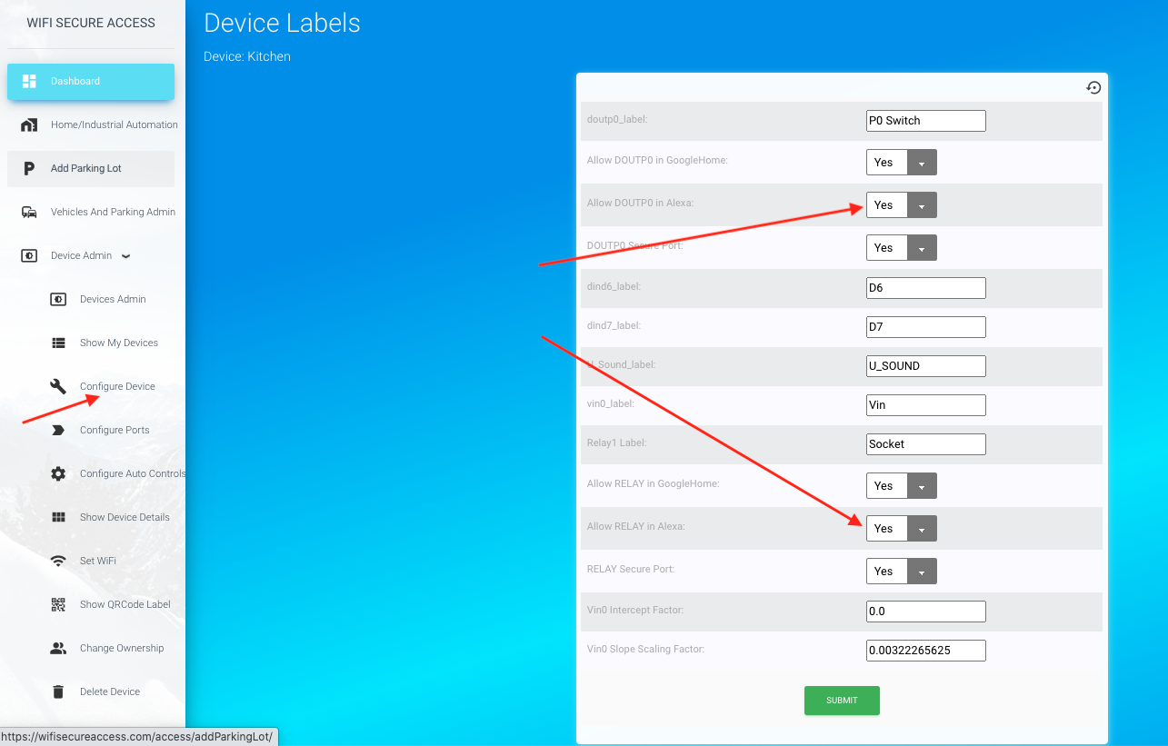
WiFisecureAccess devices are compatible with GoogleHome, and, therefore, you can use Google Home assistant to operate the equipments connected to these devices. Ports P0 and Relay of each device is disabled (by default) to be discovered by Google assistant. To make sure that these ports are enabled, click on 'Ports and Security' under Device Admin in the dashboard. You will see a page similar to Fig 14A.
Fig 14A: Enabling Google Home assistant
On this page, make sure that 'Allow DOUTP0 in GoogleHome' is set to 'Yes', if you want this port to be activated using Google Assistant. Similarly, make sure that 'Allow RELAY in GoogleHome' is set to 'Yes', if you want the relay to be activated using Google Home assistant. If you do not want to use Google Assistant to activate any of these ports, set them to 'No' and press Submit button.
If these ports are enabled to be discovered by Google Assistant, you can discover these ports in Google Assistant. Press + button in Google Home to add devices. Then press 'Set up device'. Then press 'Have Something already set up". On that page in Google Home, search for WiFiSecureAccess and select it. That will discover all the allowed ports of all your allowed devices.
Fig 14B: Google Home Page
You can now rename these whatever you would like to. Hereafter, you can say 'Hey Google, turn ON *name of the port*'. That will switch on that port. If the device is in access control mode, you can say 'Hey Google, Open *name of that device*'. That will open that door or gate. Note that you can change the name of these ports in the "Device Configuration" menu (Fig 13) in WiFiSecureAccess dashboard, and/or within the Google Home. The name in Google Home need not necessarily be the same as that in the configuration within the dashboard of wifisecureaccess.com.
Note:
When a port is enabled to be discovered by Google assistant, it determines the type of the port by looking at the device name as well as the name of the port label. The types are 'Light', 'Switch', 'Gate', 'Garage', 'Fan" and so on. If it finds any such words in either its name or port label, it will take it as its type to create an icon in Google assistant. It also uses this to determine the default mode of operation of the device. For example, if you have named the device name or its port label such that it contains a word 'Garage', it will assume that this device is connected to a garage. By default, it is also assumed that garages do not close by itself when opened. In order to close it, you have to give a voice prompt to close. If the device name or the connected port have names containing the word "door', it is assumed that this is connected to control a door access. Generally, once opened, the closing of a door or parking gate or lock is either manual, or by an automatic mechanism on the door. So, the voice prompt for closing such a device, by default, is disabled. You can override this by adding "NoAutoClose" in the name of the port label (not in the device name). If you override, it will not assume that the door or parking gate is closed automatically. Instead, it will keep the actuator activated until you give another command to close it. In other words, if 'NoAutoClose' is present in the label of its port, and if you say, 'Hey Google, open ...', it will put the actuator ON and keep it ON until you say another command 'Hey Google, Close ...'.
When the device is controlling a garage or Gate (not parking gate), it is assumed that garages do not close by itself when opened. In order to close it, you have to give a voice prompt to close.
If you want to have auto close for Garage and Gate, you can add the word "AutoClose" in the name of its port. AutoClose must be addedd in the name of the port and not the name of the device. These words are case insensitive. In fact, if you add the word "AutoClose" in the port label of garage, the smart device will close the garage door automatically by applying a pulse to the controller after the duration specified in the portcontrols of that port. Refer to Section 5 of this documentation for more about configuring portcontrols. Also, refer to section 6 for details on configuring access control modes. If garage is in AutoClose mode, you can make it stay open if you say "Hey google, Open garage" after it has come to an open position and before it gets auto-closed.
To know the current position of the door or garage door or parking gate exactly from remote, you need to install a sensor and cable that to the smart device as explained in section 6.1 of this documentation.
2.11 Using Amazon alexa to activate a port of your device
The ports of the smart device can also be activated using Amazon Alexa. You may download and install Amazon Alexa on your smart Phone. In Alexa, press 'more' and then click on 'skills and games'. Now search for wifisecureaccess, then enable that skill. When enabling the skill, it will take you to Wifisecureaccess.com and will prompt you to enter your email and password. this is your password for wifisecureaccess.com. If the entered credentials are correct, you may press Discover Devices. That will discover all the wifisecureaccess devices that you own.
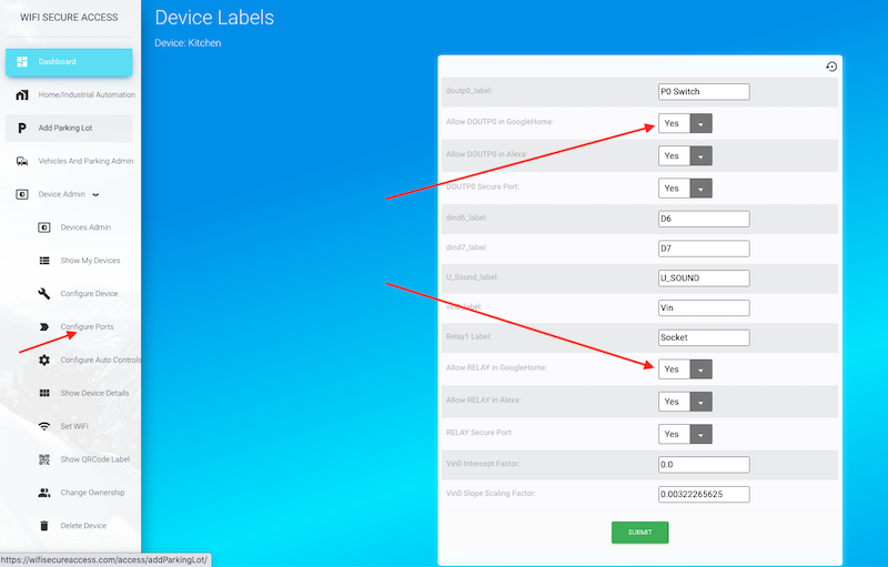
You can choose which device and which ports of that device are allowed to be discovered by Alexa. By default, all ports of all your devices are disabled to be discovered by Alexa. To change them, go to the dashboard of wifisecureaccess.com. (https://wifisecureaccess.com/access/index). Then, press 'Configure ports" on the side menu bar of the dashboard. You should now see a page similar to Fig 14C.
Fig 14C: Enabling Ports to be discovered by alexa
On this page, select 'Yes' for "Allow DOUTP0 in Alexa" if you want DOUTP0 port to be discovered by Alexa so that you can use Alexa to activate that port. Similarly, select 'Yes' for "Allow RELAY in Alexa" if you want RELAY port to be discovered by Alexa. Press Submit after making the selection(s). Then, login to Alexa on your smartphone and discover ports as you did before. If all settings are correct, you should be seeing these ports discovered in your Alexa application on your smart phone. You can now use to activate these ports by saying, for example, "Alexa, turn on XYZ", where XYZ is the name you have given the port. Similarly, to turn the port OFF, you can say "Alexa, Turn off XYZ". All the features of Alexa are now available to you for managing the equipments connected to this smart devices.
Note: The name that you see in Alexa once the port is discovered depends on the configuration mode of the device. If you have configured these devices to operate a Garage, Door, Lock or Gate, the name that you see in Alexa is the name of the device. On the other hand, if you have configured the device in Automation, then the name you see in Alexa is "device name + port name". For example, if you have enabled both DOUTP0 and RELAY to be discovered by Alexa, you will find two devices in Alexa. The first device will be named "device name + the label of DOUTP0" and the other will be "device name + the label of RELAY". For example, if you have named the device as "Kitchen", and DOUTP0 as "Light" and RELAY as 'Fan', then the names that you see in Alexa will be 'Kitchen Light' and 'Kitchen Fan'. And, if the device is configured to control Garage, Door, Gate or Lock, then you will see only one device name for each smart device and that name will be the name of the device.
2.12 Activating a port with an HTTPS POST call
You can also activate a port of a device from any of your other application programs using an HTTPS POST call. This helps integrate the WiFiSecureAccess system/devices with your other application programs. Only the relay port can be activates using this method. This feature also helps the developers to integrate this with their programs.
To activate a port of a device, make an HTTPS POST call with the following details:
POST HTTP/1.1
Host: wifisecureaccess.com/devicePortsJson/
Content-Type: application/json
data = {
"email": your_email,
"password": your_password,
"device_name": device_name,
"action": action,
}
Refer to Section 11.0 of this documentation below to see more details about this and to see a sample python program.
2.13 Enabling Two Factor Authentication (2FA) on any port
By default, the doors and gates are secure, meaning that nobody else other than those who are allowed will be able to open/close them. But, if you are interested in an additional layer of security, you can enable 2FA (two fact authentication) on these controllers. If you enable it, the user will be prompted for two factor authentication when trying to open that gate or garage door. To enable 2FA on any device, click 'Ports and Security' under Devices admin in the dashboard, just like the way it was done when enabling GoogleHome. You will see a page as in Fig 14D.
Fig 14D: Enabling 2FA on Ports
On that page, you will see a field 'Enable Two Factor Auth (2FA)'. By default, it is disabled. There are multiple optiions for two factor authentication. The options are Personal Pin, 'Send code by email', or 'face recognition'. You can choose any one of them, and press Submit. Google Home always uses Personal Pin, regardless whether you set anything other than 'No'. Once enabled, whenever you tell Google assistant to, activate that device (such as 'Hey google, Open Door'), Google Assistant will respond 'Can I have your pin?'. If you are activating this port by scanning QRCode or NFC tag or by pressing 'activate' button on your smartphone, the system will prompt for the pin before before activating that door/gate. You will have to enter your personal pin correctly to open the door. Your pin can be seen under your profile (click My Profile under User Admin in dashboard to see it). By default, the pin is 1234. You can change it to anything you like. This 2FA is an extra layer of security, and it is optional.
If you set 'Enable Two Factor Auth' to 'Send Verification Code' or 'Face Recognition', these will be used when trying to open this door/gate either by scanning its QRCode or NFC tag, or when pressing its button under 'Activate a Device' on a smart phone or computer. If you set it to 'Personal pin', it will prompt you to enter the personal pin. If you set that to 'Send Verification Code by Email', it will send a code to your email address. You will have to enter that code to open that door or gate. And, if you have set this to 'Face Recognition', it will open up your camera on your smartphone or computer and ask you to take a selfie. It will then match that photo with your profile picture to provide access.
Note: The above method of 2FA will not work with Alexa. For 2FA in Alexa, you need to set it in Alexa itself. Refer to documentation on Alexa for setting pin codes for Locks and Doors.
2.14 Configuring Notifications
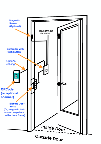
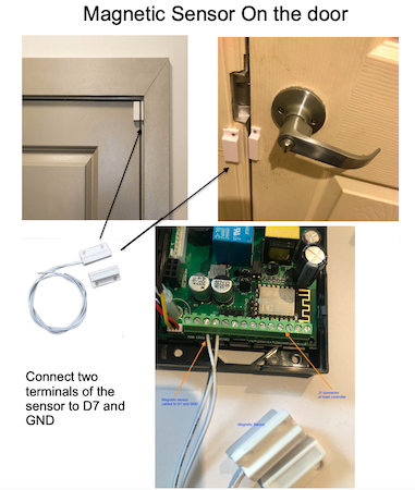
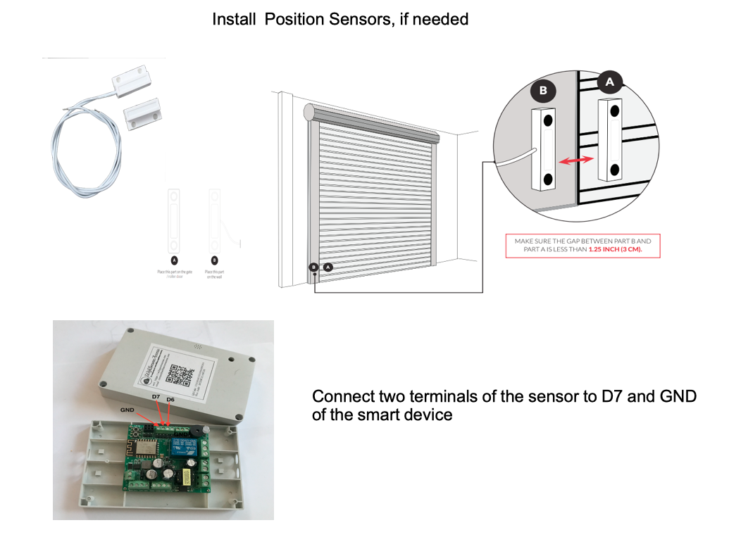
Notifications can be sent when some conditions are met. Those conditions could be when a door stays open for a long duration. Or, if you are using it for instrumentation/control/automation, it could be when a sensor senses a specified value. If this is used in access control mode, in order to send notifications, you need to install the magnetic sensor on the garage, or gate, or the door and cable it to the smart controller as explained in the Access Control section of this documentation.
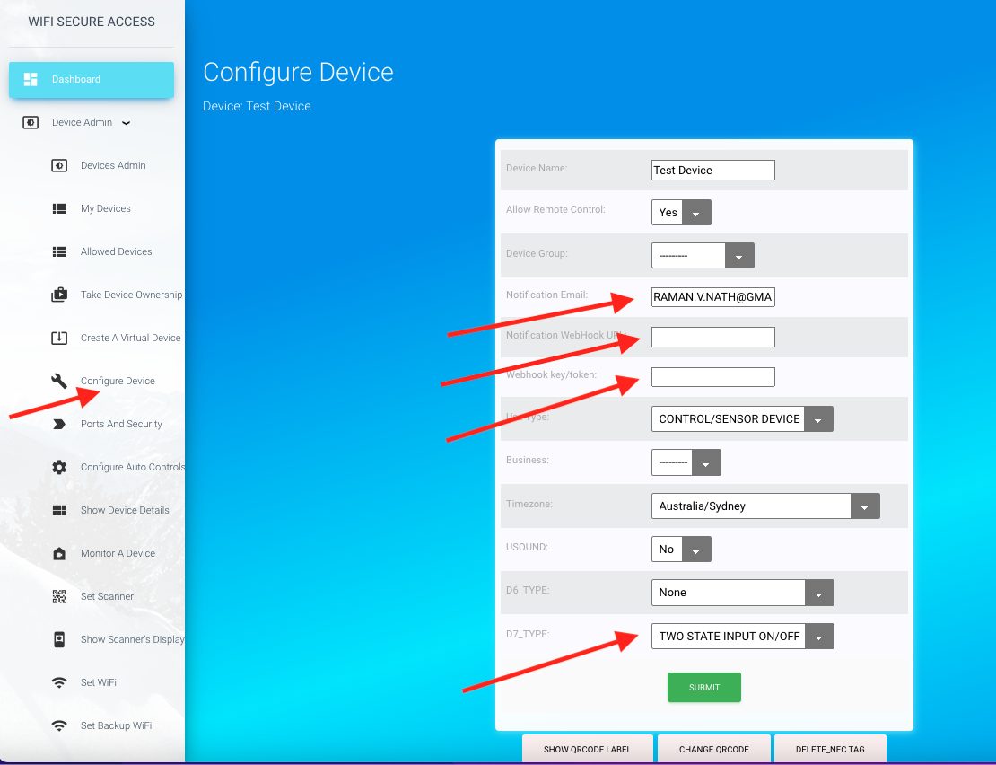
To configure notifications, click on "Configure Device" under Device Admin in the dashboard menu. That will open a page as shown below.
Fig 14E: Configure Notifications
On this configuration page (Fig 14E), you can set the fields for sending notifications. Notification Email field shows the email address to send email notifications. By default, this is set to the email address of the owner of this device. You can change it to any other email address, if you want. If this email field is left blank, no emails will be sent.
The fields Notification Webhook URL is the URL of your webhook to which a call will be made when conditions are met to send notifications. Webhook key/token is the key or the token of your webhook. You may enter those in these two fields, if you are interested in making such calls to send notifications. If the Webhook URL is left blank, it will not make any such calls to webhook URL. The call is an HTTP POST call with the key token in the header ('Authorization': webhook_key), and with some data in the body in JSON format. The data will have the device name, sensor_name, current value of the sensor, and a message. The following is the type of call that will be made:
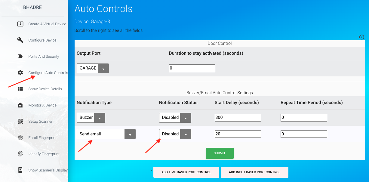
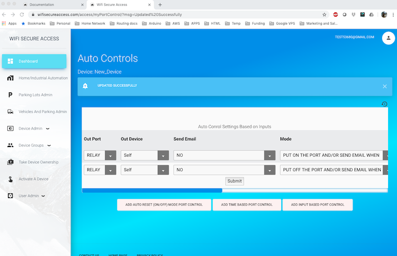
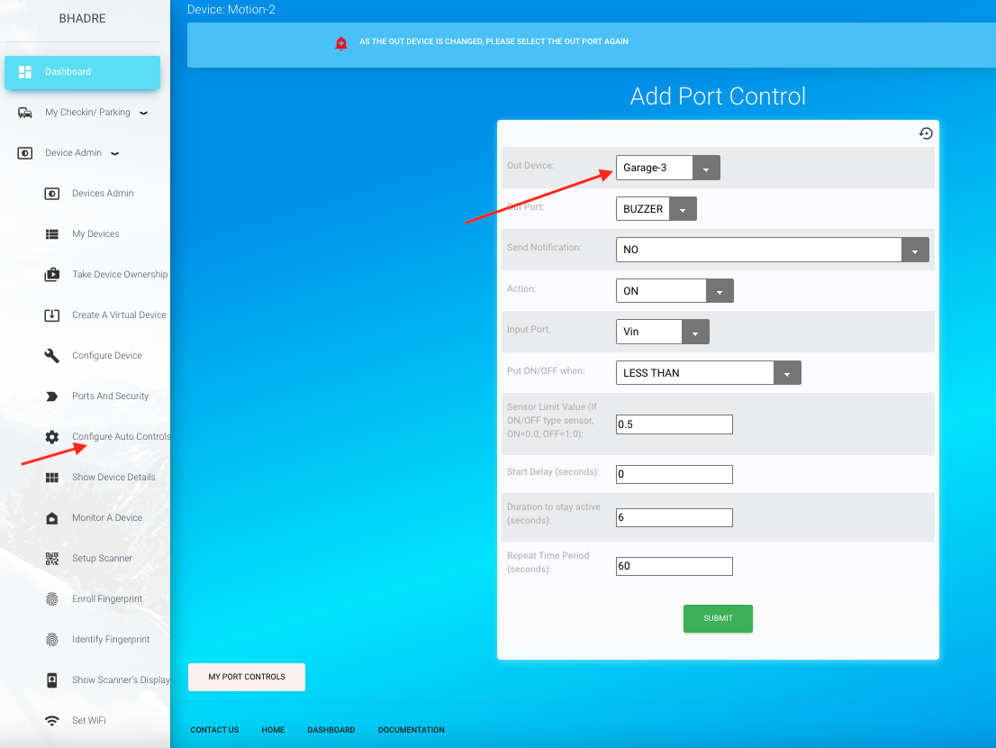
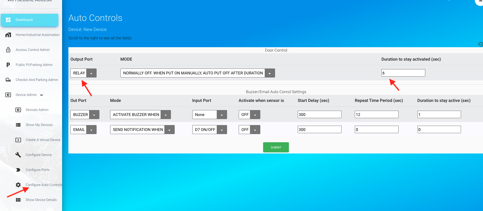
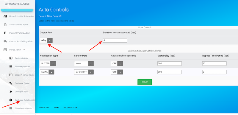
If you are using this for access control devices, the notifications have to be enabled by selecting the sensor in its autocontrols. To do that, click on Configure Auto Controls under Device Admin in the dashboard menu. That will show you a page similar to the following.
Fig 14F: Enabling Notifications
If you want email or webhook call to be sent when the garage stays open, click on 'Input Port' iin the last row of this page and select 'D7 ON/OFF'. Then set the delay time. This is the time it will wait to send notifications or to sound buzzer since the garage was opened. If you want the notifications to be sent periodically when garage stays open, you can also set the 'Repeat Time Period' in seconds.
Selecting 'Input Port' as 'None' will disable that notification.
In the "Access Control" section of this documentation, you will find further explanation of enabling notifications for accees control devices.
3.0 Connecting External Equipments and Sensors
In this section, we will describe how external equipments and sensors can be connected to this smart device.
Note: All the settings described here can be done either through the app on your smartphone or using a browser on your computer. However you need tto use a smartphone or ipad when you want to scan its QRCode or NFC Tag. We recommend using a computer for doing all initial configurations.
3.1 110/240V Electric Appliances
One can connect any 110/240V electrical appliance to this device so long as its current rating is 10A or below.
If your electrical appliances have higher current rating than this, you may use an external relay and connect that relay's coil to the solid state switch of the smart device, similar to connecting a solenoid as explained in section 3.2 of this document.
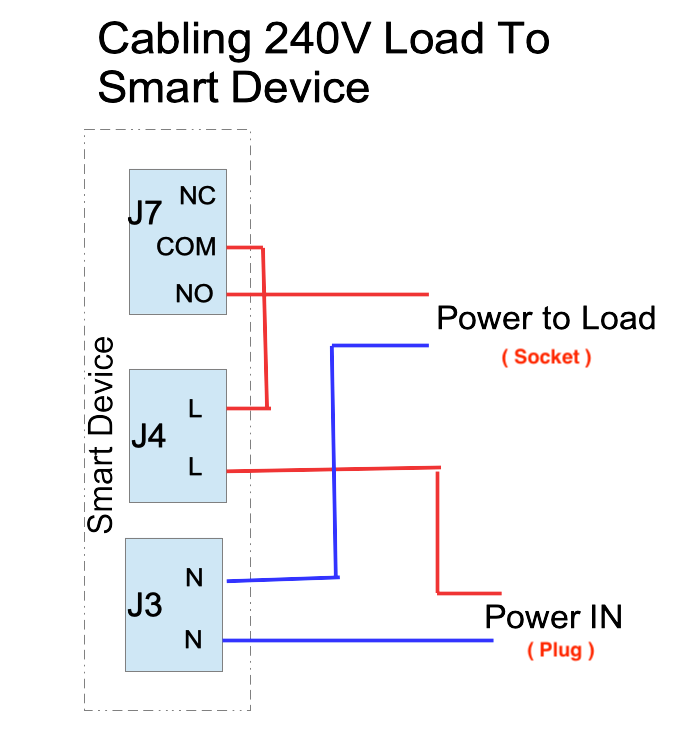
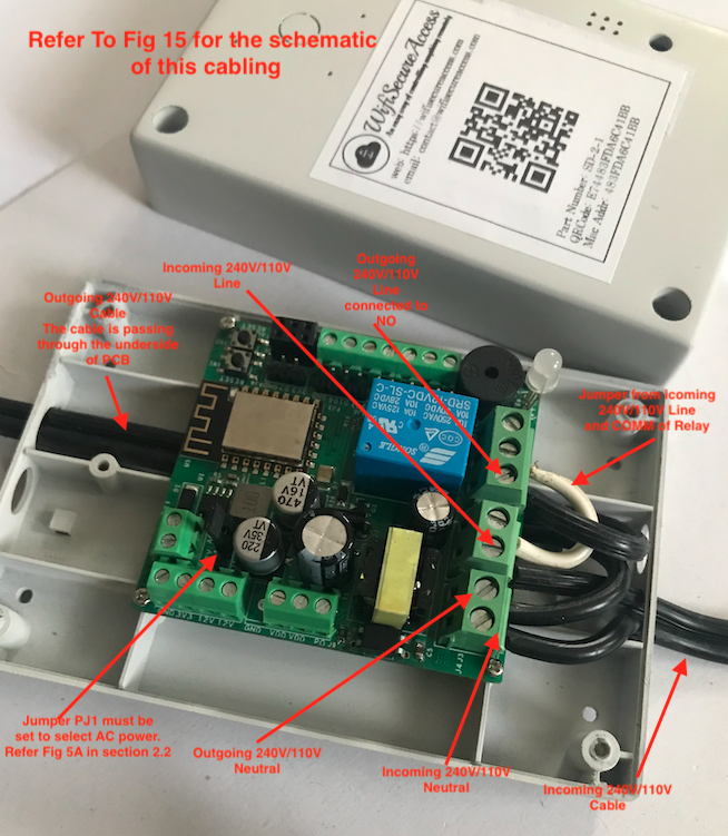
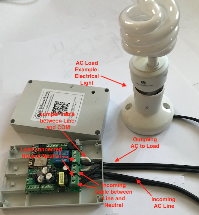
Fig 15 through 16B show how to connect a 240V electrical bulb to the device. With this connection, the device will behave like a smart plug. But, please keep in mind that this device is not a plug and play type DIY device. One has to wire the electrical appliance to this device.
Fig 15: Cabling of External 110/240V loads to Smart device
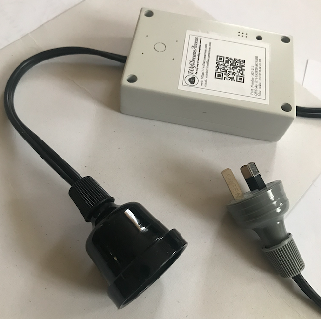
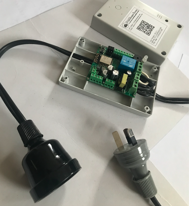
You can make a smart plug out of this smart device by cabling as per the Fig 15A through 15C.
Fig 15A: Making a Smart Plug out of the Smart Device
Fig 15B: Making a Smart Plug out of the Smart Device
Fig 15C: Making a Smart Plug out of the Smart Device
Or alternatively, you can wire the electrical appliance directly to the smart device as per Fig 16A through 16C.
Note: This is just an example to show how a 240V or 110V electrical load can be cabled. Instead of a light bulb that we have used here, you can cable any other high voltage electrical load so long as the load is rated 10A or less.
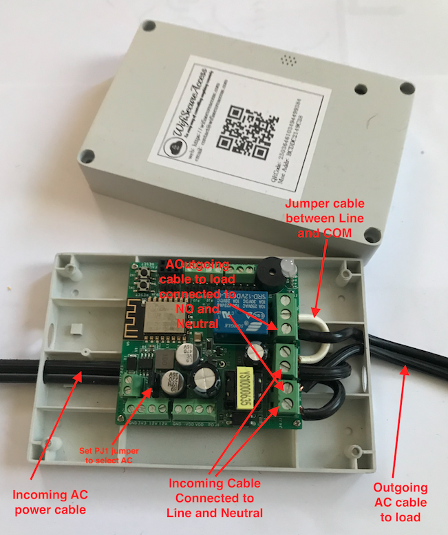
Fig 16A: A sample of direct cabling of a high voltage equipment through relay
Fig 16B: A sample of direct cabling of a high voltage equipment through relay
Warning: When using AC Power, it is important that qualified electricians are engaged, as AC power can lead to safety issues unless handled properly. Once AC power is connected to this device, one has to be careful in touching this device as the connectors J3 and J4 as well as the relay ports and other AC lines on the PCB can cause electric shock when touched. WiFiSecureAccess takes no responsibility for any harm caused due to mishandling of this device with AC power by unqualified personnel. This device is not a DIY when it comes to using AC power
When connecting 110V or 240V to the device, make sure to put the jumper on PJ1 to select AC as the power source for the PCB. Refer to Fig 5 to locate PJ1. Once all the cabling is done, close the box of the device and and switch on power. You will be seeing the device comes on and LED changes from blue to red wnd staying red indicating that the device is active.
Now, on the browser (or in the app on smartphone), click on 'Show Device Details' in the left menu bar under Device Admin. If you own more than one device, you will be prompted to select a device. If you have just one device, it will take you to a page with the details of this device. You will be seeing a page similar to Fig 10. You will be seeing the Relay with a red cross mark. Click on that. You will see the relay is put ON and the 240V/110V electrical equipment comes ON. Click on the button again to put off the electrical equipment.
As we described in section 2.8 through 2.11 above, there are four ways of operating this electrical equipment connected to this smart device. If you are using this within a house and would like to operate this using Google Home assistant, or Alexa then you can discover this in the google assistant or Alexa now. It is recommended to name the ports as per your choice. It is also recommended to disable P0 port of smart device as you are not using it when used it as a smart plug. Refer to Fig 14A and 14D for disabling/enabling ports for Google assistant and Alexa. The steps are given in section 2.8 through 2.11.
This is just an example to show how the 240V/110V cabling is to be done. In the later sections of this documentation, you will learn how electrical equipments can be controlled automatically, and how to allow others to operate this device.
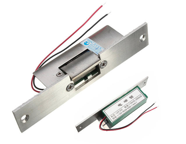
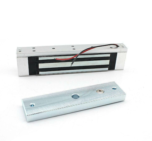
3.2 Connecting a Solenoid
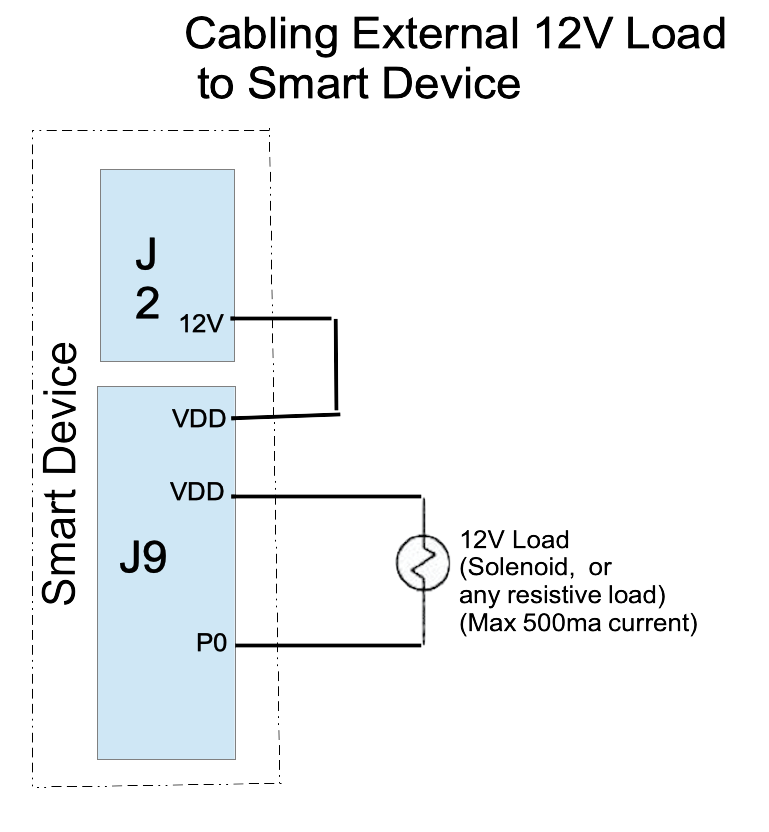
Depending on the voltage and current rating of the solenoid, there are two different ways of cabling a solenoid to the smart device. If the current rating of the solenoid is less than 500ma, and if its voltage rating is 12V, then the internal power from the smart device can be used to power the solenoid.
Fig 17 and Fig 18 show how to cable a solenoid with current rating of 500ma (or less) and voltage rating of 12V. Cable one terminal of the solenoid to P0 pin on the J9 connector of the device.
Connect the other terminal of the solenoid to one of the VDD pins of the same connector. Also, connect the other VDD pin of this connector to 12V pin on connector J2.
If you want to connect a solenoid of higher voltage, (but current rating still less than 500ma), solenoid can be cabled to P0 and VDD. But, instead of connecting internal 12V from J2 to VDD, connect positive of an external power supply to VDD. And, connect the GND of the external power supply to the GND (J2 connector) of the smart device.
Fig 17: Cabling of 12V External Loads to Smart device
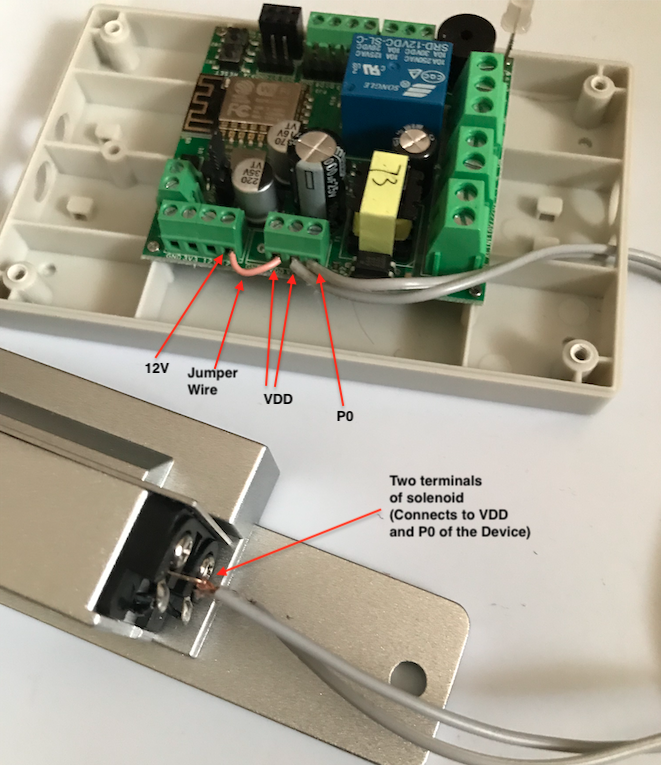
Fig 18: A sample cabling of a solenoid
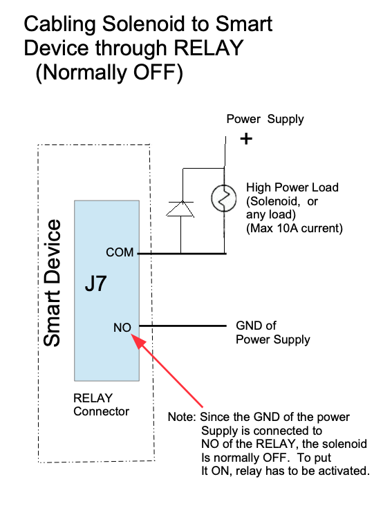
If you have a higher power solenoid with current rating higher than 500ma, then you need an external power supply to match the current and voltage rating of the solenoid. If so, do the cabling as per
Fig 18A, 18B and 18C. The cabling is done to the RELAY of the smart device. The relay terminals (COM and NO) have 10A current rating. It can take voltages up to 240V.
Fig 18A: Cabling a Solenoid through relay of the Smart Device (Normally OFF)
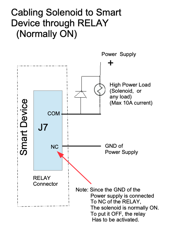
Fig 18B: Cabling a Solenoid through relay of the Smart Device (Normally ON)
Fig 18C: Cabling a HigherPower Solenoid to Smart Device
The smart controller box can be fitted anywhere, either near or far from the solenoid, wherevever it is convenient. At the location where the smart controller is fitted, it is important that there is power and WiFi. Run the cable from the smart device to the coil of the solenoid.
Once this cabling is done, close the box of the device and put its power ON. On a browser or in the app on smartphone, click on 'Show Device Details' in the left menu bar under Device Admin. Then, click on P0 or RELAY depending on how you have done the cabling. You will notice that the solenoid is put ON. To put it off, click it again.
There are four ways you can operate this solenoid manually, including Google Home assistant or Alexa. We have described this in section 2.8 through 2.11 above. So, follow those steps. In addition, if you are using this solenoid for any automatic controls or as access control to home or business, you may read the appropriate sections in this document. In the sections to follow, we will learn how to configure this for various purposes.
3.3 Connecting ON/OFF type sensors
If we are interested in reading the status of an ON/OF switch such as limit switch or any other sensors such as motion detectors that gives ON or OFF output, they can be connected to our smart device for reading its status and to take any action. An ON/OFF sensor can be connected either to D6 or D7 inputs of the smart device. Refer Fig 19.
Fig 19: Cabling an ON/OFF sensor
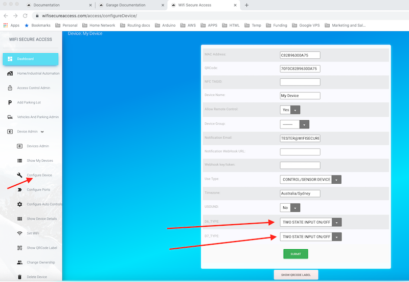
Connect the ON/OFF sensor between D6 (or D7) and GND. If it is an ON/OFF switch, connect its one terminal to D6 (or D7) and the other terminal to GND on connector J5 of the smart device. If you have a sensor such as PIR motion sensor, connect the OUT of the PIR motion sensor to D6 (or D7) and connect GND of the sensor to GND terminal of the device and connect 3.3V(VCC) of the sensor to 3V3 pin of the smart device. After doing this cabling, put the device ON. Then on a browser or in the app on a smart phone, click on 'Configure Device' under Device admin in Dashboard. On this window, make sure that D6_type as well as D7_Type are both selected as TWO STATE INPUT ON/OFF. If they are not in that state currently, select them and press submit.
Fig 20: Configure ON/OFF sensor
Then on a browser or in the app on a smart phone, click on 'Show Device Details' under 'Device Admin' in Dashboard menu. Then click on Sensor Values tab. You will see a window similar to Fig 11.
The status of the sensors connected to D6 and D7 will be displayed here. If D6 or D7 is at 3.3V, it will display as OFF, and if it is at 0V, it will display as ON. If nothing is connected to D6 or D7, it will display as OFF (reverse logic).
In the later sections of this document, we will learn how to use these sensor inputs for controlling any output ports or equipment connected to this device or any other device sitting remotely. We will also learn how to read these sensors and log the data periodically.
3.4 Analog Inputs
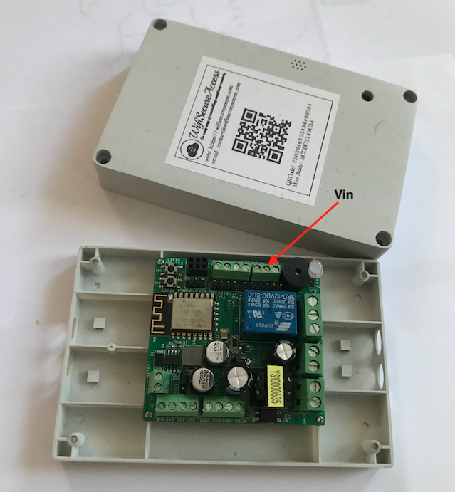
Any sensor which gives an analog output can be connected to this device. Connect the anlaog output of the sensor to the Vin pin of connector J5 of this device with ground connected to GND. Please note that the voltage range of Vin is 0 through 3.3Volts. So, the analog output must be in this range. If not, you will have to modify the analog output using external circuits to convert the range between 0 and 3.3 Volts.
Once connected, click on 'Show Device Details' in the left menu bar under Device Admin. Then under Sensor Values, you will see the actual voltage sensed.
Note: You can do a linear scaling of this analog input by changing the slope and intercept parameters of Vin.
To do that click on 'Ports and Security' under Device Admin in the left menu bar. That will open up a page similar to Fig 14 (in section 2.7 of this documentation). There you will see two parameters ('Vin0 Intercept' Factor and 'Vin0 Slope' Scaling Factor). By default, they are set to 0.0 and 0.00322265625 respectively. The actual values read by the analog to digital converter is between 0 to 1024 for a voltage range of 0 through 3.3V. These intercept and slope are set such that the displayed values are the actual voltages.
You can change these to anything you want to display different scaled values, if you prefer.
Fig 21: Cabling Analog inputs
In the later sections of this document, we will learn how to use this input for controlling any output ports or equipment connected to this device or any other device
sitting remotely. We will also learn how to read these sensors and log the data periodically.
3.5 Ultrasound Sensor for Distance Measurement
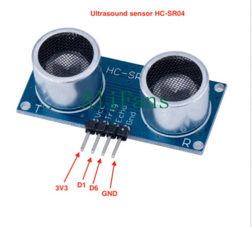
The device can be used to read HC-SR04 Distance Transducer Sensors. These sensors are low-cost sensors which are readily available in the market. You will find them on ebay and amazon. Here is a link from Amazon.
Note: This is just one link to show the type of sensor. We are not recommending to buy this. You can search and buy this from any supplier of your choice.
(If this link is broken, search for HC-SR04 in Amazanon.com)
Buy Now
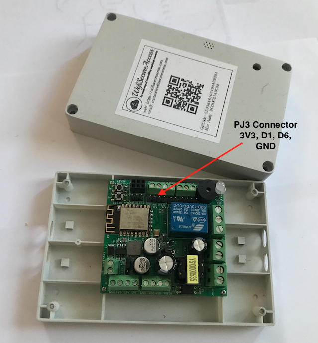
Figure 22 shows how to connect this ultrasound sensor to the smart device. Use connector PJ3 on the smart device. This connector has four pins (GND, D1, D6 3V3). Use a flat cable to connect D1 to i'Trig', D6 to 'Echo', GND to GND and 3V3 to VCC as marked in Fig 23.
Fig 22: Cabling Ultrasound Sensor
Fig 23: Ultrasound Sensor
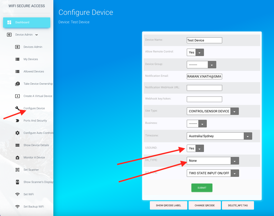
Once connected, click on 'Configure Device' in the left menu bar under Device Admin in Dasboard. Then select USOUND to 'YES' and D6_Type as None as shown in Fig 24. Then press Submit.
Fig 24: Configuring Ultrasound Sensor
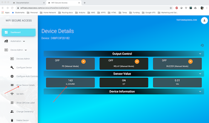
Now, you can see the distance read by the ultrasound sensor on the Device Details page. Click on 'Show Device details' in menu bar in the left under Device admin. Then click on sensor Values. You will see a page similar to Fig 26 with the current value read by the ultrasound sensor under U_SOUND.
Fig 25: Ultrasound Display
Refresh the page again to read again. Move the objects around ultrasound sensor and notice the actual distance measured. You need to refresh the page every time you move the sensor to display the new distance. We will see later in this documentation how all these can be automated to control anything depending on the inputs.
Note: If you are interested in using this smart device for data monitoring and logging, as well as data analysis, you can read this data to your local computer using a json call. In the later section 8.0 of this document, we will provide sample python programs to read sensor values at regular intervals. You can then write your own program to analyse the data the way you want.
3.6 Motion Sensing Device
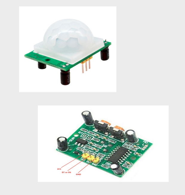
The device can be used for reading motion sensors and take actions. Low-cost motion sensors are available through Ebay or Amazon. Here is a link from Amazon. Alink to a low cost motion sensor than can be purchased from Amazon is given below, or you may choose any model of any source of your preference as long as its voltage rating is 3.3V.
(If this link is broken, search for HC-SR501 in Amazon.com)
Buy Now
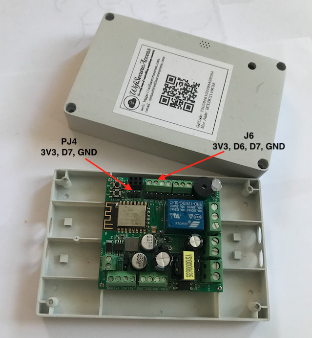
Fig 26 and Fig 27 show how to connect this motion sensor to the smart device. This motion sensor has three pins (GND, OUT, VCC). Connect VCC, OUT and GND of this sensor to 3V3, D7 and GND respectively on connector PJ4 of the device. You can also use D6 or D7 from connector J6. Motion sensor's OUT can be connected either to D6 or D7 of the smart device.
Fig 26: Cabling Motion sensor
Fig 27: Cabling Motion Sensor
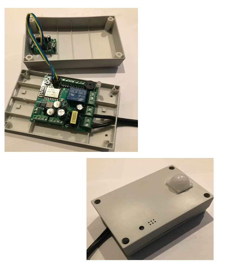
You can mount the motion sensor either external to the smart device's box, or internal as shown in Fig 27A.
Fig 27A: Mounting Motion Sensor internal to the Smart device
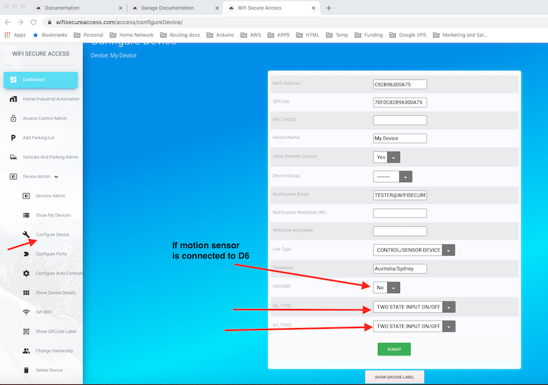
Once cabled, you need to configure the device. Click on 'Configure Device' in the menu bar on the left under Device Admin in Dashboard. Then select D7_Type as 'TWO STATE INPUT ON/OFF'. If you have connected motion sensor to D6, USOUND must be selected as None, and D6 as 'TWO STATE INPUT ON/OFF'.
Fig 28: Configure Motion sensor
Once connected, click on 'Show Device Details' under Device Admin in the menu bar on the left. In Sensor Values, you will see the state of the motion sensor. If motion is detected, and if you have connected motion sensor to D7, you will see D7 displayed as ON. In later sections of this documentation, we will describe how the devices can be configured to take any automatic actions when motion is detected.
Note: Connecting motion sensor to the smart device is similar to connecting any ON/OFF type sensors to this device.
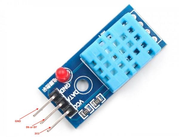
3.7 DHT11 Temperature / Humidity sensor
DHT11 temperature/Humidity sensor is a low cost sensor for reading ambient temperature and humidity. This sensor is available to buy. You can search in ebay or amazon or do a google search to source it. Here is a link from Amazon. Note: If this link is not available, search in ebay or amazon for 'DHT11 temperature humidity' sensor.
(If this link is broken, search for 'DHT11 Temperature and Humidity Sensor' in amazon.com)
Buy Now
Connect this sensor to the device as shown in Fig 29 and Fig 30.
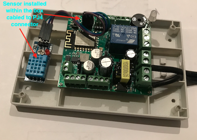
Fig 29: Cabling DHT11 Temperature/Humidity Sensor
Fig 30: Cabling DHT11 Temperature/Humidity Sensor
Fig 30A: DHT11 Temperature/Humidity Sensor installed within the box
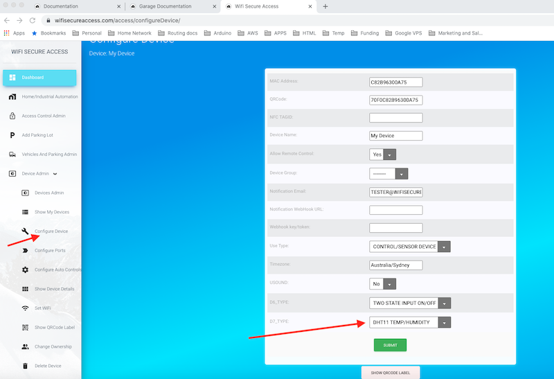
Now, in order to use this, you need to configure the device. Click on 'Configure Device' under Device Admin in the Dashboard menu. If you have connected the sensor to D6, select USOUND as None and D6_Type as 'DHT11/TEMP/HUMIDITY'. If you have connected to D7, select D7_Type as 'DHT11/TEMP/HUMIDITY'. Then press Submit.
Fig 31: Configure DHT11 Temperature/Humidity Sensor
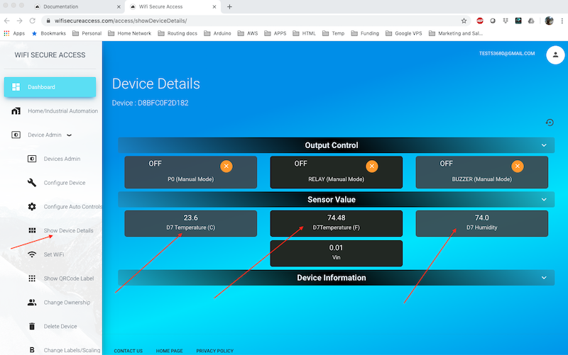
Once set correctly, click on 'Show Device Details' under Device Admin in the menu bar on the left in Dashboard. You will see the temperature and humidity read by the sensor under Sensor Values.
Fig 32: Display DHT11 Temperature/Humidity Sensor
Note: In later sections of this documentation, we will describe how to configure automatic controls based on these values read. We will also describe how these values can be read periodically into your computer for any analysis.
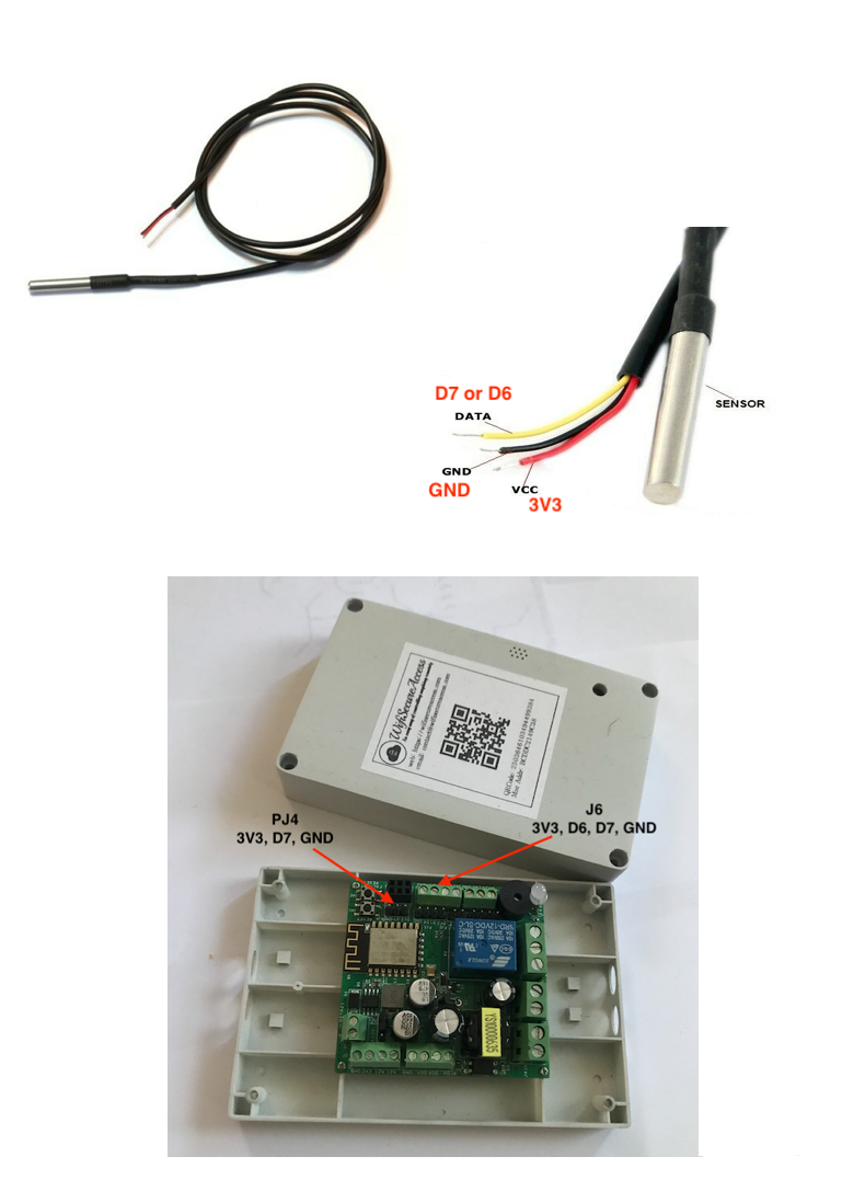
3.8 DS18B20- Temperature Sensor
DS18B20 temperature sensor can also be used with our smart device. This can be procured through Ebay or Amazon or any other source of your preference. The link given below is an example.
(If this link is broken, search for 'DS18B20 Temperature Sensor' in amazon.com)
Buy Now
Connect this sensor to the device as shown in Fig 33.
Fig 33: Cabling DS18B20 Temperature Sensor
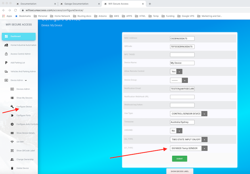
Now, in order to use this, you need to configure the device. Click on 'Configure Device' under Device Admin in the Dashboard menu. If you have connected the sensor to D6, select USOUND as None and D6_Type as 'DS18B20 Temp SENSOR'. If you have connected to D7, select D7_Type as 'DS18B20 Temp SENSOR'. Then press Submita.
Fig 34: Configure DS18B20 Temperature Sensor
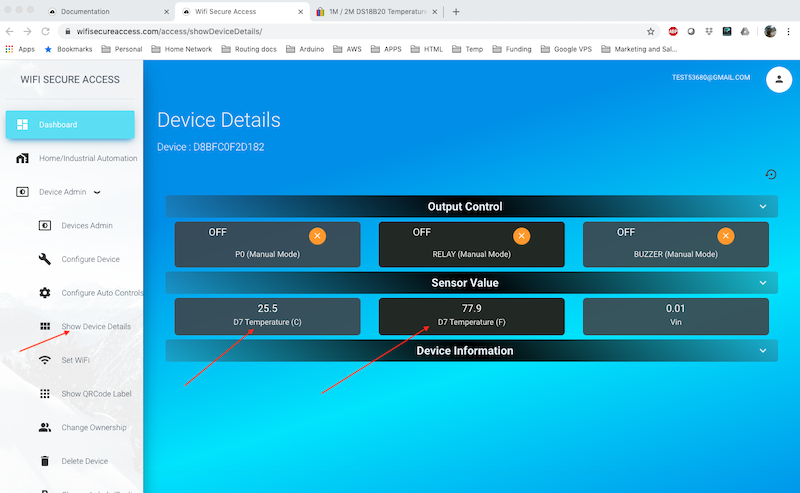
Once set correctly, click on 'Show Device Details' under Device Admin in Dashboard menu. You will see the temperature read by the sensor under Sensor Values.
Fig 35: Display DS18B20 Temperature Sensor
Note: In later sections of this documentation, we will describe how to configure automatic controls based on these values read. We will also describe how these values can be read periodically into your local computer for any analysis.
4.0 Allowing Multiple Users
This section explains how multiple users can be allowed to use a device. The owner is allowed to use all his devices all the time regardless of the settings described in this section. This section explains how the owner can allow others to use his devices and how to control and manage their authorization.
4.1 Allowing Others to Use Your Devices
You can allow or authorize the others to use your smart device. To allow someone else to use your device, they have to be registered with wifisecureaccess.com. So, request the other user to register with wifisucureaccess.com. To register, either download the app and open the app and press Admin Dashboard, or go to https://wifisecureaccess.com and click on dashboard in the top navigation bar. When it requests you to login, click on 'Create a New account'
Once they are registered, you add their email address to the Allowed Users group of your device as per the steps below:
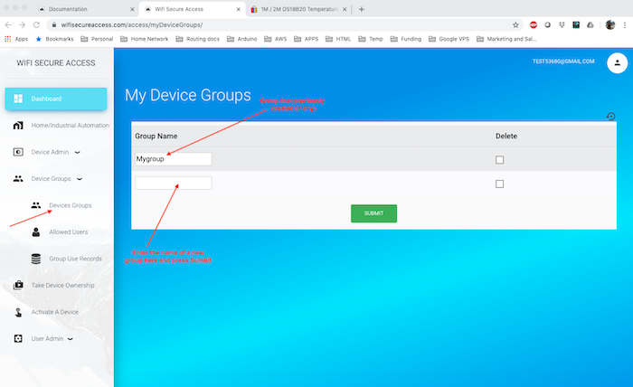
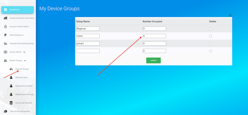
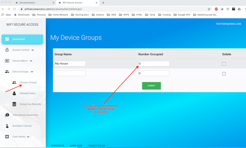
First create a Device Group. This can be done by clicking 'Devices groups' under 'Device Groups' in the Dashboard menu.
Fig 36: Configure Device group
This page will display all the device groups that you have created so far. To add a new device group, just enter the name of the group in the bottom empty row and press submit. Make sure that the name that you entered is a new name. You can create as many groups as you need.
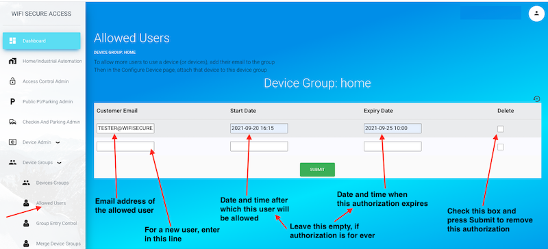
Next, click on 'Allowed Users' in the Dashboard menu. If you have created multiple groups, you may be prompted to select a group. You will then see a page similar to the one shown in Fig 37.
Fig 37: Configuring Allowed Users of a Group
In this form, enter the email address of the one whom you want to allow to use your device, and press Submit. If you have several users whom you want to allow, enter the email addresses of all of them, one at a time. You have now created a group of users.
Note: When you added the name of a user in a group, you could add a start date and an expiry date as well, if you want. Start date is the date and time this user will be allowed. He will not be allowed before that date and time. Once an expiry date is addedd, that user will not be allowed after that expiry date. The format of these dates is yyyy-mm-dd hh:mm. Leave these date blank if the user is allowed all the time with no start date and no expiry date.
You can also remove any user from this group at any time by checking the delete box against that user's name and pressing Submit.
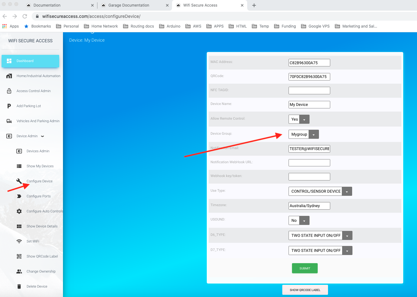
Next, you can configure your device such that all users in a group are allowed to use a device. To do that, click on 'Configure Device' under Device Admin in the Dashboard menu.
Fig 38: Configuring Devices with Device Group
In this page, select your device group, and press Submit. If all the above configurations are successful, all users in the selected device group are allowed to use this device.
When another customer is allowed to use to use your device, they will see this device in the list of devices they can use. Also, when they click on 'Show Device details', this allowed device will show up. If this device's port is enabled for GoogleHome or Alexa, the allowed users will show this device in GoogleHome or Alexa when they discover wifisecureaccess devices. But, keep in mind that the allowed users cannot change the configuration of a device.
So, if you install this device at an access door to open or close a door, all allowed users will be able to open and close that door. If you have set a start date, that user will not be able to open the door before that date. If you have set an expiry date, they will not be able to open or close this door after that expiry date. In later sections of this documentation, you will learn how to install this device as an access controller of a door.
4.2 Configuring Group Entry Controls
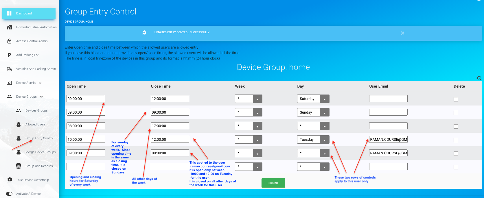
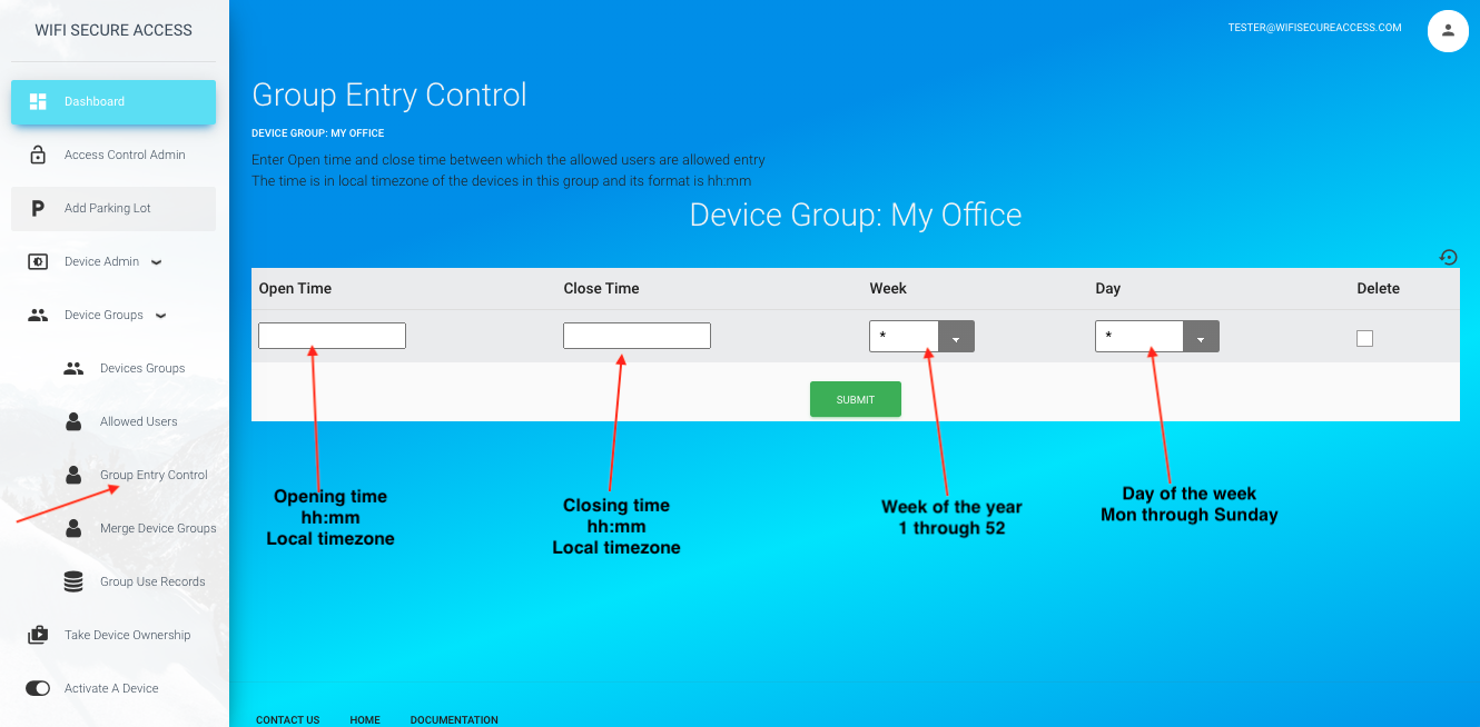
It is possible to create entry controls on the members of a device group. For example, if you want to allow the members of a group only between some specific time of a day, you can set the opening and closing times for a group. To do that, click on 'Group entry Control' under Device Groups. This tab will be available only if you have created a group. If you have created multiple groups, you will be prompted to select a group. Once selected, you will see a page similar to Fig 38A.
Fig 38A: Configuring Group Entry Control
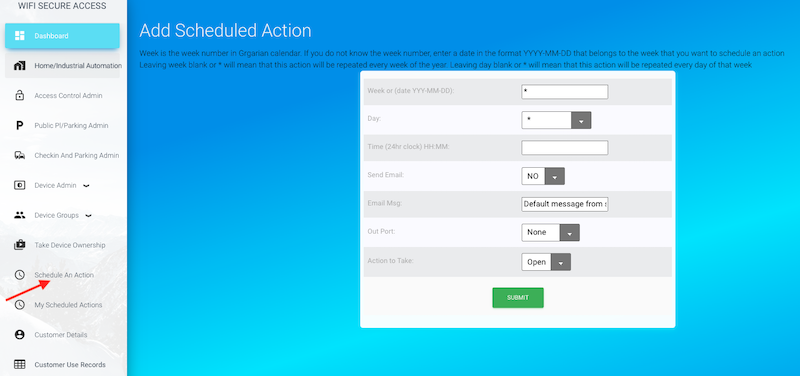
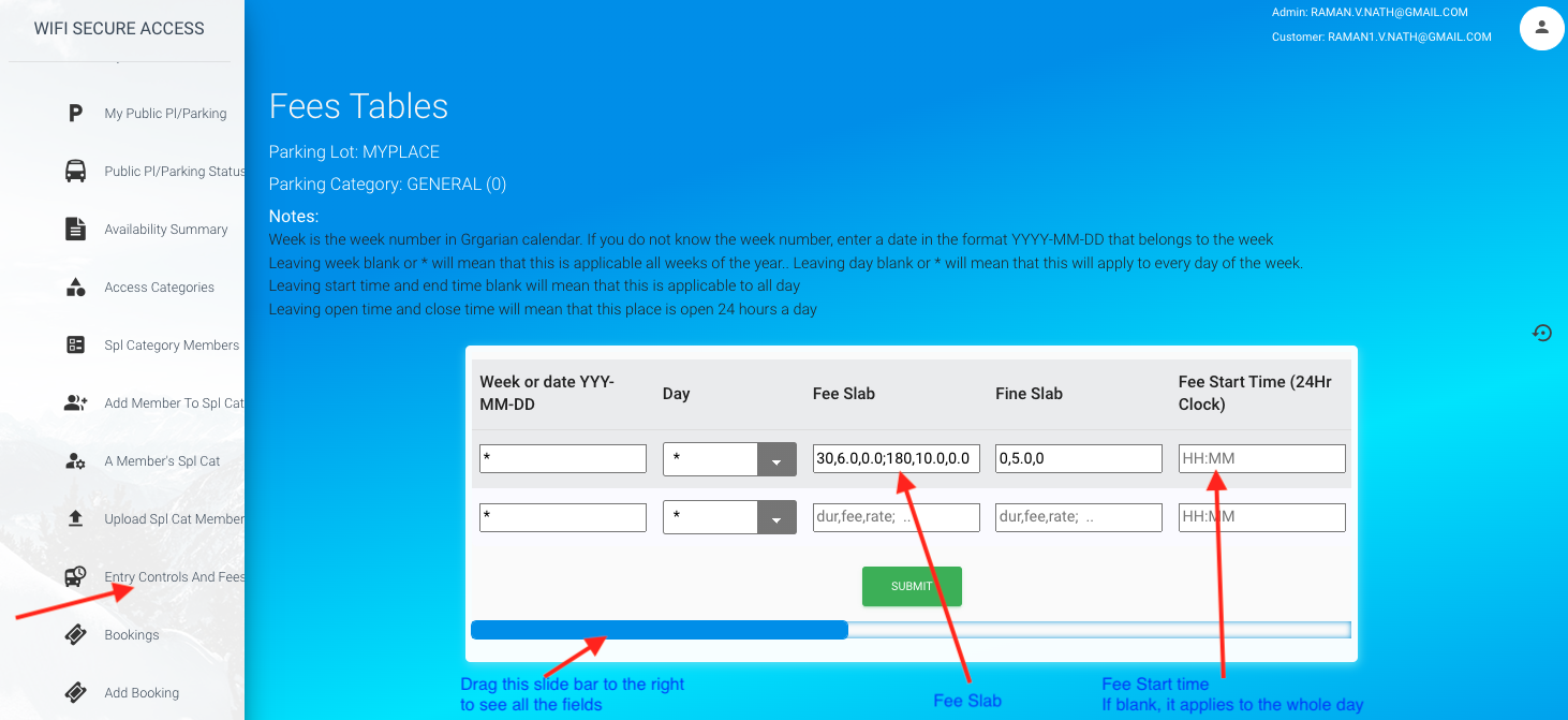
On this page, set Opening time and closing time for this group. In the field 'Week' and 'Day', you have multiple options. If you set * for week, it applies this opening and closing times for all weeks of the year. Or, you can set a week that you want this applied to. Week is the Gregarian week number. If you do not know the week number corresponding to any date, just enter the date in the YYY-MM-DD format. It will find its corresponding week number. If you enter a week number, this rule applies to that week only. Similarly, if you select * for Day, it will apply this to all days of a week. If you want this to apply to a particular day only, then select that day. You can also select the email address of a user this control must apply to. Then press submit.
Note: The general rule is that a member of the group is always allowed unless there is an open/close time in this table showing that the group is closed for him/her at that time of the day, on that day of the week of that year. An entry with opening time the same as closing time will mean no entry on that day of that week.
If no rows of controls is present, all users of this group will be allowed all the time, meaning that it is open all day, every week of the year. You can create a special closing and opening hours for a particular user by adding his email address in the 'User Email' field. If no user email is given, that opening and closing hours are applicable to everyone in that group. If opening and closing hours are missing for a user for any day of the week, the rule applicable to all will be used for that user.
You can add as many rows for each user as you want so long as those controls are different from each other. In other words, you can create an opening and closing hours for a user on Monday, another one for Tuesday and another one for, say, Thursday. And, if you leave all other days without specifying any control for that user, the general opening and closing hours used for all members of the group will be applied to this user.
You can also create multiple opening and closing hours within a day
Shown in Fig 38A is an example. In that, the first row is the opening and closing times for everybody on Saturday. The second row is the opening and closing times for everybody on Sunday. And, as the opening and closing time are the same on Sunday, it is effectively closed on Sunday. The third row is the opening and closing time for everyone on all other days of the week. The fourth and fifth rows apply to the user whose email address is given in the 'User Email' field. As per the fourth row, this user will be allowed between 10:00 and 12:00 on Tuesday, even though, all the others are allowed between 8:00 and 17:00 on Tuesdays(as per the third row). And, again, the fifth row specifically says that this user will not be allowed on any other days of the week. So, as special opening and closing times are given for a particular user covering every day of every week of the year, that rule will be applied to that user, and not the general rule. However, if a rule is not specified for a user for any day, the general rule will be applied to him for those days.
If there are no rows present, or if there is only one row with * for week and * for day, with user email empty, that means that it is open all days of the week and all weeks of the year for all the users in that group. In addition to this, you can create special opening/closing hours for each and everyone in the group. They can be either the same or different for each user.
If you do not want to anyone to enter, create a control with opening and closing hours the same. If you want to allow anyone, say, between 10:00 and 12:00 on Wednesady and do not want to grant any access on any other day, create two rows of control. In the first row of control, set opening time as 10:00 and closing as 12:00, week as * and day as Wednesday. In the second row of control, enter any time (say, 10:00) for both opening and closing time and select * for week and * for day. And, if you leave the user_email blank, these two rules will be applied to all those in the group for whom no other special rules are created.
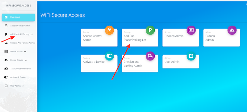
4.3 Creating a New Group by merging members of two other groups
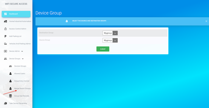
If you have created two groups and you have added members in each group, and if you are interested in creating ai new group that should contain members of both the other groups, you can do so. First create a new empty group by clicking 'Devices Groups' under 'Device Groups' in the dashboard menu. Then click on 'Merge Device Groups' under 'Device groups' in Dashboard menu. You will see a page similar to Fig 38B.
Fig 38B: Merge Device Groups
On this page, select Destination group as the new empty group that you just created. Then, select the first group that you want to add to this in the 'Source Group' field. Then press Submit. Next, repeat the same to add the second group to the same new group by clicking 'Merge Device Groups' and selecting Destination Group as the new group and selecting the second group for the 'Source Group' field. Then, press submit. Now, you have a new group with members of two of the other groups that you selected.
4.4 Entering an allowed user in a group using an HTTPS POST call from any of your applications
You can populate the allowed users of any group from any of your applications such as a booking platform using an HTTPS call. This feature helps integrate the WiFiSecureaccess door controller with your applications such as a booking platform. If these devices are installed, for example, on the door of a hotel room or an AirBnB room, the application platform that makes the booking can enter the customer's email and their start date and expiry date directly into the allowed user's list of the group associated with the controller device. If done, the customer will be allowed to open the door during the period between start-date and expiry-date. The customers can open the door either by a voice prompt, or by scanning the QRCode or NFC tag fixed on the door. Thus, this is an ideal system for hotels and AirBnB users. This eliminates the need to pass on the keys or access cards to the customer.
To add the user to the evice's group, make an HTTPS POST call with the following details:
POST HTTP/1.1
Host: wifisecureaccess.com/loadAllowedUsersJson/
Content-Type: application/json
data = {
"email": your_email,
"password": your_password,
"device_group_name": device_group_name,
"customers": customers
}
-where customers is a double list of customer details.
customers = [customer1, customer2, customer3, ....]
-where each customer is a list as below:
[email_address, start_date, expiry_date]
For example, if you want to add two customers to the allowed group of a device, the customers should be as follows:
customer1 = [customer1_email, customer1_start_date, customer1_expiry_date]
customer2 = [customer2_email, customer2_start_date, customer2_expiry_date]
customers = [customer1, customer2]
Note: Leave start date and expiry date as "", if there is no start date or end date for that customer. If there is no start date, that means that the customer can access immediately. If there is no expiry date, the customer is authorized forever.
You can also remove any customer from the device's group with another HTTPS call as follows:
POST HTTP/1.1
Host: wifisecureaccess.com/removellowedUsersJson/
Content-Type: application/json
data = {
"email": your_email,
"password": your_password,
"device_group_name": device_group_name,
"customers": customers
}
-where customers is a list of email address of the customers that you want to remove from the allowed list.
customers = [customer1_email, customer2_emal, ......].
Refer to Section 11.2 of this documentation below to see more details about this and to see a sample python program.
4.5 Displaying number of people within an Office/Building
If you have installed separate doors for entry and exit, and if nobody is allowed to open or close the door either manually or by any other means other than wifisecureaccess system, the system keeps a count of the number of people within the room or building. If any of the door is for entry as well as exit (ENTRY/EXIT), you can install a separate QRCodes or NFC tags for entry and exits, instead of using the same tag for both. You can print the QRcode labels for entry as well as exit in the 'Configure Device' menu. Click on 'Configure device' under Device Admin in the dashboard menu (Fig 38C).
Fig 38C: Configuring Exit Tags for an ENTRY/EXIT door/gate
If this device usage in ENTRY/EXIT (meaning, used for entry as well as exit), you will see two separate QRcodes and NFC tags on this page. At the bottom of this form, you will also see links to print these labels. You print the Entry QR label and place it at a location that the people can scan when entering. Place the Exit label at a location where the people can scan when exiting. Set 'Allow Remote Control' to 'No' so that nobody (other than the owner) can operate this door from remote. Make sure that the 'Allow Remote Control' is disabled on all doors of this building/office which are used for entry as well as exit. By doing so, the only way the users (other than the owner) can open these doors is by scanning the code at the door and not from remote. With this configuration, the system will keep a count of the number of people within the room/building/office.
If you are using NFC tags, you need to get an NFC tag, and enter its UID as per the steps given in Section 2.9 of this documentation.
To display the number of people currently in the office/building, click on 'Devices Groups' under under 'Device groups' in the dashboard menu. You will see the occupancy in all the groups that you have created as shown in Fig 38D. Note: Occupancy will be displayed only if you have at least one group configured with either separate doors for entry and exit or separate exit tags for exit on ENTRY/EXIT doors. Also, note that the accuracy of this depends on several factors such as 1) No one should be using any other means other than wifisecureaccess App to open/close the door/gate. 2) Remote access to open or close the door/gate must be disabled on ENTRY/EXIT type of doors/gates, and 3) Not more than one person enters or exits with one commad to open or close. You can re-correct this number any time manually by editing this field.
Fig 38D: Displaying Occupancy in an Office/Building
4.6 Displaying Group Use Records
The system keeps record of the use of all the doors/gates of this group. At any time, you can see who used this group at what time. To see the group use records, click on 'Group Use records' under "device groups' in the dashboard menu. If you have created multiple groups, you will be prompted to select the group. Once selected, you will see a page similar to Fig 38E
Fig 38E: Group Use records
5.0 Home/Industrial Automation Configurations
This section will help you learn how to configure devices for Home and Industrial Automation. The system has the capability to automate the operation of any externally connected equipments ( the equipments connected to either P0 or relay of this device). All needed automation can be done by configuring the device without the need for any programming. It is also possible to configure devices such that one device senses values of the sensors connected to it and another device sitting remotely takes an action based on those sensed values.
To use any device for Home/Industrial Automation, the device has to be configure in that mode. To configure a device in Home/Industrial Automation, click on 'Configure Device' under device admin in the Dashboard menu. Then select use_type as CONTROL/SENSOR and press Submit.
Note: If there is a word Garage, Gate, Parking, Door or Lock either in the name of the device or in any of its output port labels, the system assumes that you have cabled smart device to controllers on Garage, Gate, Parking, Door or Lock, and therefore, you are using it for access control. In that case, you will not be able to change to CONTROL/SENSOR mode. If you need to change to CONTROL/SENSOR mode, you must remove those words from the name of the device and its port labels first.
Fig 40: Configure Device for Automation
Note: When using the device for Control/Automation and, when naming the device or any of its two output ports (DOUTP0 or RELAY), make sure that you do not include the words 'Garage', 'Door', 'Parking', 'Gate' or 'Lock'. these words are case insensitive. If these words are found either in the name of the device or in any of its output ports, the device will automatically switch over to 'Entry or exit' type of Access Control device. This Access Control mode of operation is explained in the next section of this documentation.
5.1 Configuring an Output Port for auto OFF mode
We have learned in section 3 that we can activate any output port (and thus any equipment connected to that port) manually from remote by clicking a button either using a smartphone or from a comouter.
In fact, there is a shortcut to activating a port of any device. Click on 'Activate A Device' in the Dashboard menu. The app on the smartphone has this button in its home screen. When you click this button, it will show a window similar to Fig 40B listing all your devices.
Fig 40A: Activate a Device
Fig 40B: Activate a Device
Note: You can activate a device by scanning the QRCode of the device using the app. Press Scan QRCode button in the home page of the app, and scan the QRCode label of the device. That will also take you to a page displaying all your devices.
Click on any device on this page that you want to activate a port of. That will take you to a page similar to Fig 41, if the device has earlier been configured in CONTROL/SENSOR.
Fig 41: Activate a Device Port
This page shows the current status of all the three output ports of the device. You can toggle its state by pressing the button of that port.
Note that if you put a port ON, the state of that port stays ON until you press that button again to put it OFF.
If you want, you can configure the device such that it automatically puts its port OFF after a specified duration of time. Suppose that you want the port to be automatically put off 6 seconds after it is manually put ON. If so, configure as follows:
Click on 'Configure Auto Controls' under Device Admin in the Dashboard menu. If you have more than one device, it may either prompt you to choose a device, or may use the previous used device depening on the current state of your configuration. Once the device is selected, it will take you to the Port Controls page which will look similar to Fig 42, if you have not yet configured any auto controls yet. If you had earlier configured any auto controls for this device, it will list all the previously configured auto controls here
Fig 42: Empty Auto Controls Page
Now, press the button labelled 'ADD AUTO RESET (ON/OFF) MODE PORT CONTROL'. That will take you to a page similar to Fig 43.
Fig 43: Add Auto-Reset Port Control
On this page, select the output port from the pull-down options. The available options are all the output ports of this device. In the second row, it shows the mode. There is no option here. The mode is pre set to "NORMALLY OFF, WHEN PUT ON MANUALLY, AUTO PUT OFF AFTER DURATION".
Then enter the duration of time in seconds after which the port should be auto reset. If you enter 0, it will never reset that port and will stay ON until you manually put it OFF. Then press Submit. If you have entered everything correctly, it will configure the device accordingly and will display the port control page of the device (similar to Fig 44) displaying all your configured port controls of this device.
Fig 44: Port Control Page with one Auto-Reset Control
If you need, you can edit this port control on this page. If you want to delete this portcontrol, scroll the page to the right to see the Delete checkbox at the right end of this portcontrol. If you check that box and press Submit, it will delete this portcontrol.
The port is now configured such that the port automatically gets reset after the specified duration whenever you activate this port. Try to activate this port using a smart phone or computer and test if its is working.
5.2 Configuring Periodic Actions (Interval Based)
You can configure a periodic action on any of the output ports. For example, say, you want the relay to be put ON at the start of every hour. If so, configure it as follows:
Click on 'Configure Auto Controls' under Device Admin in the Dashboard menu. If you have more than one device, it may prompt you to choose the device, or may use the device that you used last depening on the environment. Once the device is selected, it will display a page similar to Fig 42 showing all the current auto controls configured on this device. If you want to configure Relay to come ON at every hour, click on 'ADD TIME BASED PORT CONTROL' on this page. That will display a page similar to Fig 45.
Fig 45: Add Periodic Portcontrol
If you are configuring Relay of this device, select RELAY for Output Port on this page. If you want an email to be sent to you (to the email address set for Alert Email field in the 'Configure Device screen') whenever it puts on the relay, select YES in 'Send Email' field. And, since you want this action to be repeated every hour, select 'NORMALLY OFF AND PERIODIC ON, PUT OFF AFTER DURATION' for the MODE field. Note that there are four options for the MODE field. They are self explainatory.
Then, set Repeat Time Period in seconds. If you do not want the action to be repeated, leave this field blank. If you want the relay to be activated every hour, enter 3600 in this field (1 hour = 3600 seconds). Next, you need to set when it should start this repeat cycle. Next Start field can be either a time delay in seconds from now, or an exact date and time in the future. If you leave this as blank, it will be taken "start immediately". If you are entering the exact date and time when this should start, then enter n 24 hour clock. Its format is yyyy-mm-dd hh:mm. You need to specify the year, month, date, hour and minutes in this format. In the next field, enter the duration in seconds the relay should remain ON. If you want the relay to be on for 1 minute, enter 60 here. Keep in mind that this duration must be less than the repeat time interval for obvious reasons.
Note: This is a periodic interval based control. That means that the rerpeat action is performed after the specified interval. This is not a control that is recommended for scheduling an action for, say, 8:00AM every day. If you configure interval based periodic control for scheduling actions every day, or every Tuesday of every week, this may not work well if the daylight saving time changes. For scheduling events of that nature, we recomment the configuration as shown in section 5.3 below.
There are three more additional fields in this form. They are optional fields. You can leave them as they are if you are only interested in just a periodic action. However, if you want the periodic action to take place only when a condition is met, then you can enter that information here. For example, say, you want RELAY to come ON periodically every hour only if a sensor detects a pre-set value. If so, connect that sensor to the inputs of this smart device. The sensors can be motion sensor, temperature sensor, rain sensor and so on. Section 3.0 of this documentation describes how to connect various types of sensors to this smart device. Once the desired sensor is connected to the smart device, you can now choose that device here in configuring periodic actions. Select input port to which sensor is connected. Then in the next field, choose the logical operation (LESS THAN. or GREATER THAN OR EQUAL TO). Then enter the pre-set value of the sensor in the Value field. Fig 45A shows an example of such entry. By selecting these three fields appropriately, you are configuring the smart device to put on the OutPort periodically only if the value sensed at the Inport is either less than (or greatet than or equal to) the Value. As mentioned earlier, if you leave input port as None, it will ignore this condition when activating periodic actions.
Fig 45A: Add Periodic Portcontrol with Condition
Once all these fields are entered press Submit. If all entered values are valid, it will configure the device accordingly and display the portcontrol page similar to Fig 46. If there is any error, it will display errors. If errors are reported, fix those errors and enter the values again and re-submit. Fig 46 will show all the port controls configured in this device (the currently configured as well as all previously confifured and still active). You can delete any of these port controls any time by checking delete button (at the far right of earch row) and by pressing Submit button.
Note: If you do not want the action to be repeated, but just only once at the Next-Start, select MODE as 'NORMALLY OFF, PUT ON AT NEXT START. PUT OFF AFTER DURATION' or 'NORMALLY ON, PUT OFF AT NEXT START, PUT ON AFTER DURATION' and set Repeat Time interval as 0 when adding portcontrol
Fig 46: Port Control Page with a Periodic Portcontrol
Now, you can monitor this device. You will observe that the relay is put on for one minute at every hour starting 2020-08-21 18:00 (as per the settings in this example). It will put relay ON the first time at 18:00 on 2020-08-21. The relay will remain ON for one minute. Again, the relay will come ON at 19:00, and again at 20:00 and so on.
Note: What is demonstrated here is just an example only. You can create such portcontrols on any port of any of your smart devices to meet your needs.
You can delete this portcontrol or any portcontrols that you have configured by checking the delete box against that portcontrol in the portcontrols page (Fig 46) and pressing Submit button. Note that the delete checkbox is all the way at the right of the form. You may have to scroll the bottom bar of that form to find it.
Note: You can configure periodic port controls on any of your device to send you emails even without activating an output port. For example, say, you want emails sent to the 'Alert Email' address every hour starting at 8:00AM, 2021-02-15 as a reminder. You can do that exactly the same way as you have configured above, except that when selecting fields, select None for Output port and YES for 'send Email' fields. Note: Alert email is the email address set in the Alert Email' field in the 'Configure Device' screen. Unless set, it defaults to the email address of the owner of the device.
5.3 Configuring Regular Scheduled Actions on daily or weekly basis
You can configure scheduled actions either for one time or for repeated actions either on a daily baisis or a weekily basis. For example, say, you want the garage door open at 8:00 AM every day automatically. That is a scheduled action. Scheduled actions can be anything such a sending a notification email, or to turn on a an equipment connected to a smart device. This method is different from the periodic controls discussed in section 5.2 above. In section 5.2, the configuration was to periodically control an equipment on a regular basis. That control is interval based. If the interval is one day, that action appears as if it is doing it on a daily basis. however, that method will not adjust with daylight saving time. in addition, that method cannot be used with devices in Automation mode (use type = CONTROL/SENSOR). Instead, in this section, the method used is for any device regardless of what mode the device is working in. This method, therefore, can be used to activate any devices in Access Mode as well as automation. In addition, this will adjust when daylight saving time changes. You can set as many scheduled actions as you want.
To schedule an action, first make sure that the device is running firmware version 4.4 or above. Then, click on 'Schedule an Action' under Dasboard menu. This tab is also available in the main index page of the dashboard. This menu will be available if you own a device. The device cannot be virtual and your virtual devices will not be shown in the piulldown selections. Once you click on that menu, it will prompt you to select one of your devices for scheduling an action for. Once the device is selected, you will see a page similar to the following:
Fig 46A: Schedule an Action
On this page, set the parameters for the scheduled aaction. Set the week and day of the year. The week is the Gregarian clendar week number of the year. If you do not know the week number, enter any date within that week in the format YYYY-MM-DD. It will find the week number. If you want the action to be repeated for every week of the year, leave this as * or blank. Similarly, select the day within that week. Choose it from the pull-down options. Leave it as * if you want this action to be repeated every day of that week. If you want this action to be done only on a specific day of the week, then select that day. And, if you want this action to be executed only during a specific week, enter that week number.
Note: If a week number is given, the scheduled action will be deleted at the end of that week, and will not repeat the same week next year.
Then, set the time of the day when this action to be executed. The time must be in 24Hr clock in the format hh:mm.
If you want a notification email to be sent at this time, select 'YES' for Send Email field.
Email Msg field is the message that will be sent in the email. This must be a short message not exceeding 256 characters
Next, select the Out Port. Out Port is the port to be activated at the scheduled time. You have only two options - either None or RELAY (or whatever you have renamed that RELAY pport to). If you want only an email to be sent without activating anything connected to the device, select Out Port as None. If you want the garage door to be activated at the scheduled time, select the Out Port as RELAY (or whatever name that you have renamed this RELAY port to).
Then select the action to be taken at the scheduled time. Select from the pull-down options (Open or Close)
If your scheduled action is only to send a notification email, you can select out port as None.
Note: Once the out port is put ON, it will stay ON until you turn it OFF. If you want that port to be put off automatically, you have to create an auto reset port control for that port as explained in section 5.1 above. That port control automatically turns the port off after a preset duration. If your device is in access control, this auto OFF control is already there. You can check this by clicking "Configure Auto Controls' Under Device Admin in Dashboard menu. If the device is controlling a garage door or Gate, then, you need to put that in AutoClose mode as explained in section 6.3 (sub heading Configuring AutoClose). That section explains that you can add a word AutoClose in the port label name to achieve this.
You can create as many scheduled actions as you need. You can see all your scheduled actions if you click on 'My Scheduled actions' in the dashboard menu. There you can delete any scheduled action. But, you cannot modify any of the scheduled actions. To delete a scheduled action, check the Delete box against the Action at the right and click Submit button. You may have to scroll the page to the right to see this Delete check box. You can delete and create a new action, if you want.
Fig 46B: Schedule an Action
5.4 Configuring port control based on Input Condition
You can configure an output port to be put ON/OFF based on an input sensor values. Fo example, you can configure RELAY to be put ON when the voltage level at Vin is greater than or equal to 1.0volts. Or you can configure P0 to be automatically put ON when the temperature read by DS18B20 Temperature Sensor connected to D7 is 60 degree or higher. Or, you can configure Buzzer to be activated when the motion sensor connected to D6 senses a motion, and so on for any of your requirements.
Let us see, for example, how to configure the device such that RELAY is automatically put ON when the analog voltage read from Vin is greater than or equal to 1.0Volts, and it gets put OFF when the vltage is less than 1.0Volts. To configure this automatic control, click on 'Configure Auto controls' under Device admin in the Dashboard menu. As mentioned in the previous secion, it may prompt you to choose device if you have more than one device. Once selected, it will come to portcontrols page displaying all the portcontrols that you have configured on this device so far. Click on 'ADD INPUT BASED PORT CONTROL' on this page. That will take you to a page similart to Fig 47.
Fig 47: Add Input Based Portcontrol to put Relay ON
Similar to what we did when configuring periodic port control, select the various fields in this form. For our example, select RELAY for output port. Choose 'Self' for the 'Out Device'. In fact, this system has capability to activate a port on another device when sensor condition on this device are met. We will discuus that in the next subsection. Here, for our example, select 'Self' for this field. In the 'Send Email' field, select either YES or NO depending on whether you want an email to be sent to the Alert Email address when the output port is activated. For the 'Mode' field, there are two options - 'PUT ON THE PORT AND/OR SEND EMAIL' or 'PUT OFF THE PORT AND/OR SEND EMAIL'. For our example, select 'PUT ON THE PORT AND/OR SEND EMAIL'.
Choose the input sensor in the field 'Input Port'. Depending on what you have connected to D6, and D7, you will be presented with the available choices. For this example, select Vin.
In the next field, you have to choose a logical comparator, either 'LESS THAN' or 'GREATER THAN OR EQUAL TO'. For our example select 'GREATER THAN OR EQUAL TO'. This is for the comparison of the sensed value with the Sensor Limit Value.
The device will compare the sensed value from the input sensor Limit Value to make a decision on activating the output port.
In the field 'Sensor Limit Value', enter a value. For our example, enter 1.0.
This means that the device will continuously read Vin and compare it with 1.0Volts. If the value at Vin is greater than or equal to 1.0, the condition for activation of the output port is met.
There are three more field in this form. They are to be filled if the output port must be put off after a duration even if the input condition remains met, and whether the output port must be put on again in a repeat cycle if the condition remains met.
For our example here, let us leave those fields blank and press submit.
If every entry is correct, it will configure the device and will show you portcontrols page of this device showing all the portcontrols that you have configured so far as shown in Fig 48. You may have to scroll the form right to see all the columns of this port control.
Fig 48: Portcontrol Page with an Input_based Portcontrol
You have just one input based port control. That port control will put on RELAY when Vin is 1.0volts or more. Relay will remain ON so long as Vin is greater than or equal to 1.0. Relay will be put OFF when Vin is less that 1.0Volts. You can test this on the device by applying voltage at Vin.
The above control has some drawbacks when the Vin fluctuates rapidly around 1.0Volts. The Relay will keep on putting ON and OFF if Vin flucuates around 1.0Volts. In systems where you do not want such things to happen, you can add a separate portcontrol to put the relay off. In other words, say, you want the relay to be put on when Vin greater than or equal to 1.0Volts, but once it is ON, you want relay to be OFF only when Vin is less than 0.5Volts.. This can be done by adding one more portcontrol for RELAY. Click on 'ADD INPUT BASED PORT CONTROL' once more and add another port control to put RELAY OFF when Vin is less that 0.5volts as shown in Fig 49.
Fig 49: Add Input Based Portcontrol to put Relay OFF
Enter the values as shown in Fig 49 above and press Submit. It will then show you portcontrol page similar to Fig 50 with two portcontrols for RELAY. The first one is to put RELAY ON and the second one is to put RELAY OFF.
Fig 50: Portcontrol Page showing two port controls for Relay, one to put on and the other to put off
You may test this now by applying voltages at Vin. You will see that the Relay comes ON when Vin is greater than or equal to 1.0. It will stay ON until Vin goes below 0.5Volts.
Note: Make a note of the difference between having just one portcontrol to put the relay ON and having separate portcontrols for putting relay ON and OFF respectively.
As mentioned before, you have three other fields in an input-based portcontrol They are 'Start Delay', 'Repeat Time period' and "Duration to stay active'. These fields can be used if you want the relay to stay active only for a fixed duration when activated and repeat this periodically, instead of keeping it on whenever the input conditions are met. If you want to wait for a delay time to activate relay after the input condition is met, enter that delay time in seconds in 'Start Delay' field.
For example, if you enter 10 seconds for 'Start Delay', delay will be activated only 10 seconds after the input condition is met. And, if you set a duration of, say, 60, the relay will get put off automatically after 60 seconds even if input condition remains met. And, if you enter 60 seconds for "Repeat Time Period', relay will be put on again after 60 seconds. This cycle will repeat until input condition for putting OFF relay is met.
You can generate input based port controls on any output port as per the steps outlined above. You can use any types of inputs connected to the input ports. They can be limit switches, ultrasound sensors, motion sensors, analog inputs, DHT11 temperature/humidity sensor, DS18B20 temperature sensor and so on.
Note: If you are using ON/OFF type sensor, keep in mind that the value read is either 0.0 or 1.0. The the Value field should be either 1.0 (OFF) or 0.0 (ON) when adding an input based port control. If you enter anything above 1.0 for Value when the sensor is an On/OFF type, it will automatically set it as 1.0. Similarly, if you enter less than 1.0 for Value, it will automatically reset it as 0.0..
Note: Please also make sure that the use_type field in the 'Configur Device' must be 'CONTROL/SENSOR' when the device is used for Home/Industrial Automation or Data collection and monitoring. This has been explained in the begginning of the section 5.0 on Home and Industrial Automation.
5.5 Configuring One Device to Control Another Device
Our IOT system has the capability of controlling ports on remote devices based on the conditions sensed by another device. You can configure a device to control another device. You set the port controls of a device such that when a condition on inputs is met, an output port of another remote device is activated. Both devices must be owned by you to make this type of port control. Configuration is the same as describes in the previous sesction on 'Configuring port control based on Input Condition', except that when choosing Out device, choose the device whose Output port you want to control, instead of 'Self'. Available devices will be seen in the drop down selections. The Out devices have to be in SENSOR/CONTROL mode in 'Use Type' (This setting is in 'Configure Device' under Device Admin). When the 'Use Type' of a device is in Entry or Exit (gate/door), port controls cannot be added. Fig 51 shows an example of adding such a configuration.
Note: When one device controls the other, sensors are on the first device and the equipments that it controls are connected to the other device. Input based port controls must be set up on the first device to which sensors are connected and NOT on the other device to which equipments are connected.
Fig 51: Add Portcontrol to control port on another device
If you own two devices, try setting this and try testing it.
6.0 Access Control Configurations
This section will help you learn how to configure devices for Access Control to residential houses, office/industrial buildings, private apartment parking spaces and other restricted areas.
This can be achieved by configuring the smart devices without the need for any programming. Entry to the restricted area is limited to those who are allowed. The section 4.0 on 'Allowing Multiple Users' in this document described above explains how to add allowed users to use a device kept at the entry or exit of a restricted building or area.
in this section we will explain how to install these smart devices at the entry or exit as well as how to configure them.
To use any device for Access Control, the device has to be configured in that mode, first. To configure a device in Access Control, click on 'Configure Device' under Device Admin in the Dashboard menu. Then select use_type as either 'ENTRY TYPE', or 'EXIT TYPE' or 'ENTRY AND EXIT'. If this device is installed at the entry of the restricted area, select 'ENTRY TYPE', if the device is installed at the exit, select 'EXIT TYPE' and if this device is installed at a gate or door used for entry as well as exit (front door of a house, for example), select 'ENTRY AND EXIT'. Then press Submit.
Note: If there is a word Garage, Gate, Parking, Door or Lock either in the name of the device or its port label, the Use Type will automatically change to ENTRY/EXIT. And, if you use it for Garage, Gate or parking, it is assumed that the smart device is cabled to controller on those Garage/Gate/parking such that a pulse (similar to pushing a button) will open/close that Gargae/Gate/Parking. On the other hand, if it is named Door or Lock, it is assumed that the smart device is cabled to an actuator on the Door/Lock which needs a constant steady voltage across it to open and keep it open. Removing that voltage will close it.
Fig 52: Configure device for Access Control
Note: When naming the device or any of its two output ports (DOUTP0 or RELAY), if you include the words 'Garage', 'Door', 'Parking', 'Gate' or 'Lock', the device will automatically change its mode to Access Control. These words are case insensitive.
6.1 Configuring Access Door Control of a House
As described earlier, you can use this device to control access to a residential house or a building.
As an example, let us see how we can install this to open or close the front entry door or a house. Once installed, the system provides a key-less entry to the house. Opening the door from remote also becomes possible. With the suggestion given here, you can still use the mecahanical key of your house to enter the house in the event of a system failure or emergency.
To install this device, the door is to be fitted with an electric door strike or a magnetic lock.
Fig 53-0: An Electric Door Strike
Fig 53-1: A magnetic Door Lock
If you have already installed one,
and if its voltage rating and current rating matches with our device's solid state switch, you can connect this device directly to that actuator (or electric strike). If you do not have one fitted on the door yet, we recommend purchasing one and installing it. There are various types of electric strikes available. You can buy them from Ebay or Amazon. Given below is a link to an electric strike in Amazon. This is a Fail-Secure type. We recommend using a 'Fail Secure' type of an electric strike on the door, even though 'Fail Safe' type can also be used. If you are using 'Fail Safe' type, do the cabling as per Fig 18B. Listed below is just an example. You can search in Ebay or Amazon for Fail Secure Door Electric strike.
(If this link is broken, search for 'Fail Secure Door Electric Strike' in amazon.com
Buy Now
You can also use a magnetic door lock, if your door is suitable for that. This is also available to buy through eBay or Amazon. Given below is a link to buy from Amazon. Note: These are just examples and not necessarily our recommendations. You can buy any similar product so long as its voltage and current ratings match with our controller (12VDC, 500mA).
(If this link is broken, search for 'Magnetic door lock' in amazon.com
Buy Now
Fig 53 shows a picture of an installed door strike. You can search in YouTube for installation guides for installing an electric strike. Alternatively, you can get this installed by a tradesperson. Once the door strike is fitted on the door, install the smart device behind the door inside the house so that it is secure. Fix it on the wall or anywhere conveniently closer to the door.
Fig 53: An Electric Strike fitted on a door
Fig 53A: Installing an Electric Strike on the door
Fig 53B: Installing a magnetric lock on the door
Fig 53C: Installing magnetric locks on double doors
Fig 53D: Fitting Controller on Door
Then cable the solenoid of the electric strike or the magnetic lock to the smart device as per the steps given in this documention in section 3.2 labelled 'Connecting a Solenoid'.
Fix the smart controller anywhere inside of the house/building such that nobody can tamper with it from outside. You can either install it hidden inside the wall, or exposed. It can be either near the door or anywhere far from it where there is power and WiFi. Run the cable from the electric strike's coil to the smart controller, preferably hidden within the wall.
You may place the label of this device with its QR code on the outside of the house. You may either use a QR Code label, or an NFC Tag, as described in Section 2.9. You may mount that on the front side of the door so that you can scan its QR Code (or NFC Tag) conveniently to open the door from outside. This kind of installation with the device sitting inside and with only a QR Code (or NFC Tag) pasted outside makes the system highly secure as no one cam tamper with this device. If you also implement 2FA (2 Factor Authentication) as explaied in section 2.12 of this documentation, this door can be trusted to be highly secure.
On the other hand, if you want to use Google home assistant or Amazon alexa only, and not using QRCode NFC tag, you need not install QRCode or NFC tag outside the door. Google Home is also highly secure if you use @FA (refer section 2.10 of this documenation).
Note: Make sure to add a word "Door" either in the name of the door or its port label. Having a word 'Door' (case insensitive) in either in the name of the device or in the name of the poprt connected to the solenoid will make sure that the device operates in Access Control..
Allowing others to use this device/door: Once these installations are done, power on the device. Configure a device group to allow all house mates to enter the house as per the steps given above in section 4.0 'Allowing Multiple users' of this documentation.
When creating a group, give the name of the group something like 'My House', or your house name or anything similar. If you are using this on the doors/gates of offices/buildings, have a look at all the extra features and settings available under Section 4 of this documentation.
Then click on 'Configure Device' under Device Admin in Dashboard menu. Configure the device as shown in Fig 54.
Fig 54: Configure Device for Door access Control
Connecting Sensors to detect if the door is closed and Configurating Auto Controls:
Once the device is configured in Access Control as described above in Access Control mode, click on 'Configure Auto controls' under Device admin in Dashboard menu. You will see that some portcontrols are automatically created.
fig 55 is similar to what you may see on this page.
Fig 55: Configure Door Portcontrol
It shows three portcontrols pre-created. The first one is an auto off control.
This portcontrol makes sure that the electric strike gets automatically deactivated 6 seconds after it is activated.
You can change this duration to anything you like. As we have connected the solenoid of the electric strike to output port P0 of the device, change the OutPort of this portcontrol to P0.
Note: When using to control a garage or a gate, the duration here in the first port control has no effect unless you have configured AutoClose as descrtibed under section 6.3. It should, however, be a non-zero value.
Note: When using to control Door or parking gate, it is assumed that they are closed either manually or by any other automatic mecahnism after opening it. So, the smart controller does not keep the actuator activated beyond the time specified in the Duration filed of the first portcontrol in Fig 55. You can override this by adding "NoAutoClose" in the name of the port label (not in the device name). If you override, it will not assume that the door or parking gate is closed automatically. Instead, it will keep the actuator activated until you give another command to close it. In other words, if 'NoAutoClose' is present in the label of its port, and if you say, 'Hey Google, open ...', or press the button on your smartphone to open it, it will put the actuator ON and keep it ON until you give another command to close it.
The second portcontrol is an input based port control for activating buzzer. As the selected input is currently blank, this port control is currently not active.
If you want the buzzer to go on when the door is left open for a long time, you can activate this portcontrol. To activate it, you need to install a sensor to detect whether the door is currently open or closed.
You can install a limit switch or a magnetic switch on the door such that it closes when the door is closed. Magnetic switches suitable for this are available in eBay. You may search for "Wired Door Window Sensor Magnetic Switch" in ebay. Here is a picture of the sensor installed on a door.
Fig 55A: Magnetic Sensor on a door
Then connect that sensor to either D6 or D7 of the smart device (with one terminal of the sensor to D6 or D7 and the other terminal to GND on the smart device).
After that, change the portcontrol for buzzer. If you have connected switch to D6, select D6 ON/OFF as the input Port. Also, make sure that in the Device configuration (Fig 54), 'D6 Type' is selected as 'TWO STATE ON/OFF'. Then, select when the notification should be activated. If the sensor is connected such that the sensor in ON when the door is closed, you want the notification to be activated when the door is open, meaning when the sensor is OFF. So, select OFF fot the field 'Activate when sensor is'. However, if you have installed the sensor such that the sensor is ON when the door is open, then you may select this fiels as ON.
Next, you need to set the other parameters of this port control if you want the buzzer to keep beeping periodically. The port control already has some preset values. If you are satisfied with them, leave them as they are. Otherwise, you may change them to wahtever you like.
So, you may refer to the steps given in that section to understand these better.
The third portcontrol on this page is about sending notifications when the door stays open. If you want the device to send notifications when the door stays open, you select the input port as the same as the input port selected for the buzzer.
You will see some default values for this control. You can change them, if you want. Alert email is sent to the email address set in the field 'Alert Email' in the 'Configure Device' window. This is defaulted to the email address of the owner of the device. You can change that to any other email address by clicking 'Configure Device' under Device Admin in the Dashboard menu. There change Alert Email to anything you want.
Note: If you want to deactivate any of these last two portcontrols, you can do so by selecting the input port as None. That will also disable reading the sensor, and the current status of the
door that it reports may not be correct.
Note: It is important to set any one of the notifications (either sounding buzzer or sending email) for knowing the current position of the garage accurately from remote. This is because the sensor is read only if any one of the notifications is enabled.
Once all these modifications are done, press Submit button. If every modification is correct, it will configure the device accordingly.
The door is now set to go. All those who have been authorozed to use this device can open the door either by scanning the QR Code (or NFC Tag), or from remote by pressing 'Activate a Device' in the app or on the Dashboard on a computer or by Google Home Assistant or Amazon Alexa, as explained in Section 2.8, 2.9, 2.10, 2.11 and 2.12 above.
To open the door from remote using a smart phone, open the app and click on 'Activate a Device'. It will show all your devices. Select the name of this device to open it. If you are authorized, the door will be opened for the pre-configured duration. If you want to open this door from remote using a computer, in a browser go to the dashboard after loging in. Click on 'Activate a Device' in the Dashboard menu and then click on the device.
If you want an additional layer of security, you can add Two Factor Authentication(2FA) on these devices so that the system will prompt for a pin prior to opening the door. Refer to section 2.12 to know how to add 2FA.
Note: The system keeps use records for 30 days. You can check the device use records by clicking 'Device Use Records' under Devices Admin in the side menubar in Dashboard. You can also see the group Use records by clicking 'Group Use records' under Device groups. In addition to these, every user can see their use records of all the devices they used for the last 30 days by clicking ''My Use records' under User admin in the side menubar of the Dashboard.
In a later section of this documentation (Section 9.0 of this documentation), we will describe how the owner of the device can extract use records from our system to their computer and do any kind of analysis of use data.
Note: The configuration explained in this section is the same regardless whether this is installed on the door of a house, or the door of an office building where several people work, or whether it is installed at the entry gate or exit gate of a private parking of an apartment. Just by scanning the QRCode or NFC Tag or by using Google Home Assistant, the users can open the gate. No need for any separate tags or keys or anything like that. What the user needs is just his smart phone. Access control can be managed from anywhere remotely by the owner. The owner can add and remove allowed users any time remotely. He can also put an expiry date on anybody's access. For example, if someone has to be given access for one day, or for a few hours, the owner can set the expiry date as per the configuration described in section 4 above.
6.2 Configuring Access Control of a building or private parking
This smart device can be used to control access to private parking within a building or elsewhere where only the residence or members of a club or staff are allowed to enter or park.
These buildings and private parking may have multiple entry doors and multiple exit doors. Install one of this device at every entry and exit doors and connect them to the actuators of the door or gate. The actuators can be boom gates or any Doors with electric strikes fitted on them (as explained in section 6.1 above).
Then set the USE_TYPE of the device at the entry as “ENTRY TYPE”, and set the USE_TYPE of the device at the exit gate as “EXIT TYPE”. If the gate or door is used for entry as well as exit, then set the use_type as 'ENTRY/EXIT'. These settings are to be done by clicking 'Configure Device' under Device Admin in Dasboard menu. Then, as described in the section 4.0 on 'Allowing multiple Users', create a device group and add the email addresses of all the residents of that building into that device group.
Then select that device group in the 'Configure Device' page of all these devices. as explained earlier in the section 4.0 'Allowing Multiple Users'.
Then, if you want to use QRCode for entry or exit, print QRCode label of this device and paste it at a convenient location for the driver to scan. To print QRCode label, click 'Show QRCode Label' under Device admin in the Dashboard menu. Then save that image to a file on your computer, resize it to appropriate size of your choice and print it. You must have received a few labels when you purchased this smart device. You can use them, or print as many additionals label you want.
As described in Section 2.9 of this document, you can also use NFC Tags instead of QRCodes. To do so, buy an NFC tag and find its ID and then press Configure Device and enter that Tag Id in the "NFC TAGID' field and press submit, as explained in section 2.10 of this documentation. Then, install that NFC Tag at a convenient location for the driver to sacn.
Alternatively, if you prefer to use Google assistant or Alexa to activate these ports by voice, you can do so as explained in section 2.10 and 2.11 of this document. For additional layer of security, you can add 2FA as explained in section 2.12 of this documentation.
Then, as explained in the previous section of this documentation, install door strikes on each of these doors, if you do not have them installed yet. If these are for private parking in the apartment/office complex, you may have boom gates or any other type of gates. Connect either the RELAY or P0 of the smart device to the electric strike/Gate controller, depending on what kind of gate control is installed. Provide either 12V power or AC to the device depending on what is available at the door/gate. It is also important that WiFi must be available at the door/gate. The WiFi of the device must be set to the available WiFi as per the steps given above in section 2.5 on 'Setting WiFi of the Device' in this documentation..
Fig 56: Cabling a solenoid to Smart device
Fig 56A: Cabling Boom Gate to the Relay of Smart device
Note: When naming the device and its ports, make sure to include the word 'Parking' or 'Door' or 'Gate' either in the name of the device or the port connected to the actuator. This is important so that the device will operate in the correct mode to operate these gates.
Note: It is assumed that the parking gates, or gates, or garage door controllers are such that applying pulse at its trigger terminals (push button) will open or close it. If it is currently open, a pulse will close it, and if it is currently closed, a pulse will open it.
Anything other than gate, parking or garage is assumed to work like a door with electric strike type of actuators. They open when a steady DC volatge is applied and close when the voltage is removed (or, visa versa).
Setting Open/Close times of the building/private parking:
If this device is used for access control of buildings and offices as well as private parking, you can set an opening time and a close time so that the allowed users can enter only between those times. The owner of the device/building can enter any time, though. If you do not set this, it is assumed that the building/office/parking is open 24 hours a day all days.
To set open/close time, click on 'Configure Entry Control' under Device Groups in the side bar menu. If you have more than one device group, it will prompt ypu to select the group ypu want to set the openin/closing times. Once the group is selected, it will take you to a page as shown in Fig 56B.
Fig 56B: Configuring Entry Control of a device group
On this page, set the opening time and close time. Then select the week of the year and the day of the week where this opening time and close time is applicable. If you leave week as *, it is assumed that this is applicable to every week of the year. If you leave both week and day as *, it is assumed that these opening/closing times are applicable to every day of the year. On the other hand, if you want this to be applicable to Monday of every week, select day as Monday and select * for week. Then press Submit. If you have only one such entry, the opening/closing is applicable only for that day of every week, and all other days, it is assumed that it is open 24 hours. To add opening/closing timings for any other day also, create another row by selecting another day. So, you can have 7 such entries for each day of the week. If you want this to be applicable only for a particular week of the year, select the week. If you want multiple opening/closing hours on the same day, you can create another row for the same day. In fact, you can create as many row of entry controls as you want. Once set, the allowed users will be allowed only between the opening/closing times. The owner of the device/building can enter any time and these settings are not applicable.
These opening/closing times are useful when this system is installed for offices. Gyms and so on when nobody is to be allowed when the office/gym is closed.
Once these cabling is done, and the device is configured as per the steps above, the system is ready for use. Allowed users can use their smart phone to enter the building or parking lot by scanning the QRCode (or NFC Tag) pasted at the entry. In order to open the gate, open the app on the smartphone, the go to scanning page and press scan. Then scan the QRCode, if you are using QRCodes. Press 'Scan NFC TAG', if you are using NFC Tag. If you are using Google Home Assistant or Alexa, open google assistant and discover device under WiFisecureAccess. When using alexa, search for the skill 'WiFiSecureAccess' and enable that skill to discover these devices. Then, activate thegates/door by voice as explained in section 2.10 and 2.11 of this document. The gate will open if you are authorized to open it. Authorization can be managed by the manager of the building (the owner of this device) remotely on their computer. He can add and delete anybody from the allowed users. He can also allow temporary users such as visitors for a short duration. The steps for this are explained above in section 4.0 on 'Allowing Multiple Users' of this documentation.
If interested in adding one more extra layer of security, you can add Two Factor Authentication (2FA) as explained in section 2.12.
There is another useful setting that may be needed in large buildings. There is a setting in device configuration to disable remote control of any device at any door, Refer to Fig 56C.
Fig 56C: Configuring a device to disable remote activation
You can set 'Allow Remote Control' to 'No', if you want to. If you set it to 'No', those who are allowed in the selected group will not be able to
activate this device from remote. If selected 'No', the only way anybody (other than the owner of the device) can activate it is by scanning its QR Code or NFC Tag.
Note: If you are using QRCode label for scanning at the entry or exit gates, allowed users can copy that label and scan it from remote to activate the gate, even if the above setting "Allow Remote Control' is set to 'No'.
If you are very strict about disallowing anybody activating these gates from remote, we recomment using NFC tags instead of QR Labels.
As explained earlier in section 2.0 above, buy NFC Tags, then scan it using our app on your smart phone.
That will show the tag's ID (if you are owner of any device). Then press 'Configure Device' under Device admin in the Dashboard menu.
Enter this Tag Id in the 'NFC TAGID' field and press Submit.
Then, fix this NFC tag at the entry or exit gates. These NFC tags cannot be copied and, if you have set 'Allow Remote Control' to 'No', you can be assured that nobody other than the device's owner can operate that device from remote.
The owner of these devices can see the number of users within the building or private parking by clicking the 'Device Group' under Device Groups in the Dashboard menu. We recommend changing the name of the device group to the name of the building or anything similar so that you can easily identify a group.
Fig 57: Occupancy in a Group
The owner of the device can also see the use records of this building by clicking 'Group Use Records' under 'Device Groups' in the Dashboard menu. He can also see the use of individual door/gate by clicking 'Device Use Records' under Device Admin in the Dashboard menu
Fig 58: Group Use Records
Fig 59: Door/Gate Use Records
Our system keeps the records only for 30 days. In a later section 10.0, we will describe how the owner of these devices can extract these use records from our system to their local computer for any data analysis.
6.3 Configuring this Device to Open/Close an existing Automatic Garage Door
Note: If you have purchased a dedicated garage door controller (hardware version 0), instead of seeing this section, click here to see its detailed documentation.
This smart device can be used to open or close a garage door using Google Home or Alexa or by using the app on the smartphone. If the garage door has an existing automatic control, then it should be having a manual switch for opening and closing its door. You need to locate that. It can be either on the PCB of the automatic control unit, or it can be mounted externally on the wall of the garage, or on the box of the control unit. In some installations, you may find two terminals marked 'Push Button' on the controller unit. When you find that, try shorting between the two terminals of that manual push button using a plier or a wire. If that opens or closes the garage door, then our smart device can control it by a smart phone or Google Home or alexa.
To use the manual push button, cable smart device to this push button as shown in Fig 61A. Connect the two terminals of that push buttom to COM and NO of the relay connector J7 on the smart device. If this push button is on the PCB of the garage door controller, it is also possible that the PCB on the automatic controller of the garage door has 12V power output pins on a connector. If so, that can be connected to our device (J1 connector of our device) as power supply for the device, eliminating the need for external power cable for the device. If you use J1 as the power source to our device, make sure that PJ1 jumper on our device is set to select that as the power source as explained earlier in this document on installation of the device. If there is no power available from the PCB of the garage door's automatic controller, you will have to connect external power to our device either 12V or AC as explained above in section 2.2 on 'Setting up the Device' of this Documentation. You can fix the smart controller at any location where there is power and WiFi, and run two cables from it to the pushbutton terminals of the garage door controller.
Fig 61A: Cabling Push Button to Smart device
Fig 61B: Cabling Push Button to Smart device
Fig 61C: Cabling Push Button to Smart device
In some garage door systems, you may also find a connector on the PCB of the garage door controller on which there may be a terminal to trigger open or close. Connecting that terminal to GND may open/close the garage door. Try grounding that terminal. If that closes or opens the garage door, then that is also compatible with our smart device.
If the garage door controller has a terminal block on its PCB with trigger terminal (usually used for connecting additional external manual push buttons), you can connect that terminal to NO and COM to GND of the smart device. In such cases, that terminal block may also have 12V power.
Note: If you are unable to locate the manual pushbutton or unable to connect the smart device across the oush button, there is another way by using a remote controller. If you open the remote, you may either see a track on to which its push button comes in contact when presses, or you may see the push button itself mounted directly on its PCB. You may solder twi wires to these terminals and connect NO and COM of the J7 connector of the smart device. Refer to 61D and 61E with such cabling to a wireless remote controller. In fact, you can buy one Universal Remote controller and train it to your garage door. Then connect the push button of that remote controller as shown the Fog 61D and 61E so that you and the other members of your family can use a smartphone to open/close the garage.
Fig 61D: Smart device connected to a wireless remote of the garage door
Fig 61E: Cabling of a wireless remote to the Smart device
Configuration:
Once our device is cabled as described above, then it is a matter of configuring our device to operate this garage door. Configuration of this device for garage door is identical to the configuration described above in section 6.1 on 'Configuring Door Access Control of a House', except that the output port used here is RELAY. So, follow the steps given in that section. Make sure to name the device and the port such that the word 'Garage' is either in the device name or the relay1 port label. In the portcontrol configuration, set the Output Port as RELAY. The 'Duration to stay activated' field can be any number other than 0. Any postive number (in seconds) will have an effect only if AutoClose is set as described below under the heading "Configuring AutoClose".
Fig 61F: Configure Device for Garage Door
Fig 61G: Configure Garage Door PortControl
Once configured, you can operate garage door using the WifiSecureAccess app on your smart phone. Use it exactly the same way you use it for opening the door of a house. You can either operate it from remote by pressing 'Activate a Device' on the app, or by scanning the QRcode of the device (if you paste the QRCode label of the device outside the garage). You can also add this device to Google Home or Amazon alexa and use google assistant or Alexa to open or close the garage door. Refer to section 2.10 and 2.11 of this documentation.
Note: Make sure to add the word "Garage" either in the name of the device or its port label. This is necessary for the device to get configured correctly for garage. Refer to sections 2.8, 2.9, 2.10, 2.11 and 2.12 of this documenation on details of using smartphone, Google Home and Alexa. Section 2.12 shows how to set up 2FA for an additional layer of security, if you so desire. Refer to section 4.0 of this documentation for allowing multiple users to operate this garage door.
Detecting whether the garage door is Open or Closed:
As described in section 6.1, you can fix a sensor (a limit switch, or a magnetic switch) on the garage door (if it does not have one already) such that the switch becomes ON (activated, or closed) when the garage door is closed. Then connect the two terminals of that sensor to D6 and GND on the J6 connector of the device. If you prefer, you can connect to D7 and GND instead of D6 and GND on the same J6 connector. Then, click on 'Configure Auto Controls' under Device Admin in Dashboard (Fig 61G). On that page, select 'Input Port' as 'D6 On/Off' in the second or third row of the port control and press Submit. Select 'D7 On/Off' if you have connected sensot to D7 port of the device. If you want the device to beep or send emails when the garage door remains open, or for further explaiantion of the three port controls that you see on this page, refer to the descriptions under the subheading Connecting Sensors to detect if the door is closed and Configurating Auto Controls in section 6.1 of this documentation.
Fig 61H: Installing magnetic sensor on garage
Once a sensor is connected and port control is configured as described here, you can know the current state of the garage door reliably on your smart phone. Open the WiFiSecureAccess App and press Activate a Device' on the scanning page. That will show the current status reliably. That also will help when using Google Assistant such that it will report that "the garage is already open" if you tell google assistant to open it when it is already open. Similarly, if you tell google assistant to close the garage when it is already closed, it will tell you that "the garage is already closed". In the absence of such a sensor, you cannot know the current status of the garage door reliably from remote. Such a sensor is not absolutely necessary to operate the garage door, though. In the absence of such a sensor, the smart device will not know if you either manualy open the garage door, or open it using it wireless remote.
Note: It is important to set any one of the notifications (either sounding buzzer or sending email) for knowing the current position of the garage accurately from remote. This is because the sensor is read only if any one of the notifications is enabled.
Configuring AutoClose:
With our smart device, it is also possible to configure auto-closing of the garage door. For example, say, you want the garage door automatically closed 2 minutes after it is opened. This can be one by adding a word AutoClose in the port label of the port of the smart device connected to garage door controller. Say, for example, you have connected Relay port of the smart device to the garage door controller. If so, click on 'Configure ports' under Device Admin in the left side bar menu of the dashboard. Then change the name of the relay1 Label to 'Garage Autoclose'. then press submit. Then, you need to set the duration for which the garage door should remain open before closing it automatically. Click on Configure Auto Controls under Device admin in the Dashboard menu. Then select this device and change the value of 'Duration to stay activated (sec)' to whatever you prefer. If you want the garage door to remain open for 2 minutes before closing, then set this to 120. Press submit.
Note: The duration is the time since you press the button to open the garage and not the time since the garage door comes to a full open position. So, make sure not to set this duration lower than the time needed for the garage/date to come to a full open position.
With the above configuration with AutoClose, the garage will automatically get closed two minutes after it is opened. With this autoClose in place, suppose that you want to keep the garage remain open anytime after you open it, you can use either Google Home or alexa, and say 'Hey google, Open *name of the device* during the time the garage is open. So, if you try to do so during the period when the garage is open (whwn in autoclose mode), it will cancel autoclose at this time and will stay open. Then, if you want to close the garage, you can say "Hey Google, Close *name of the device*". This is a special handy feature of our smart device that you can configure and use.
PS. It is assumed that the cabling of the smart device is to the push button terminal of the garage door controller. Therefore, the smart device applies a pulse to it for opening or closing. If you are using it for opening a gate where it needs anything other than a pulse, this AutoClose feature will not work. Please contact us for any help
7.0 Public Access Places and Public Parking Lots
WifiSecureAccess provides a smart and cost effective system to manage access to public places and parking lots. Access to public places such as public transport, cinema halls, hotels, public/community event centers, or any such places can be managed easily and convieniently using our systems. In addition to managing access to people for such public places, one can use WiFiSecureAccess system for managing public parking. With this platform, there is no further need to have any ticketing and ticketing machines. Customers can use their smart phones to access these. They can swipe the QRCode or NFC tags fixed at the entry gates/doors to get access. If there is an entry fee or parking fee, the customers will be charged either at the entry or exit automatically through their credit card.
With this system, customers can also book and hold a place from remote. All the registered public places as well as Parking lots will be shown on a google map. Public can also see on the map the current availablity of all these registered public places and parking lots. They can see how many spots or seats are currently available, the opening and closing hours, and the the entry fee or parking fee, if applicable.
The owner of these public places or parking lots can configure access fees or parking fees. They can configure opening and closing hours, In this section of the documentation, you will learn how to register such public access places with WifiSecureAccess system, how to install smart devices at the entry and exit and how to integrate that with the gate actuators and how to configure the access control.
In this document when we say 'parking', it is also applicable to 'people checkin' and vise versa.
7.1 Installing Smart Devices and Cabling them to door/gates/Boom Gates
Cabling the Device to actuators on the doors and gates, or to boom gate of the parking lot is identical to what is described above in section 6.2 on 'Configuring Access Control of a building or private parking' above. Cable the RELAY (NO and COM) to the actuators on the door/gate or the controller of the boom gate. Install smart devices at every entry gate and exit gate of the public place or parking lot. Print QRCode label (or NFC Tag, if you are using NFC Tags) of the device and locate it at the convenient place at the gate so that the customers can scan them easily.
7.2 How to register a Public Access Place or a Public Parking Lot with WiFiSecureAccess
You need to first register your public place or parking lot with WiFiSecureAccess providing a unique name and its address. Address must be identifiable by Google maps. To register, click 'Dashboard'. If you have not used WiFiSecureAccess yet, you will be asked to login or register yoursef and will be taken to a login page. Once loged in, you will be taken to the index page where you will see several options. If you have not purchased and registered any WifiSecureAccess controllers yet, you will see some tabs to 1) 'Take ownership of a device' and 2) Create a Virtual Device. If you have purchased a controller, click on 'Take ownership of a device' and follow the prompt. Or, if you want to work with a virtual devive, click on 'Create a virtual device'. A virtual device is just a label with a QRCode, or NFC tag. A virtual device is enough to manage access to public places and parking lots if you do not want it to control its gates or doors. Physical controller is required to control the doors and gates at the entry and exit. Once you have taken ownership of a controller, or created a virtual device, you will see a button named 'Register Public Place/Parking Lot' in the main dashboard page. If you already have another parking lot in the system, you will see a button name 'Public Place/Parking Lot Admin'. If so, click 'Public Place/Parking Lot Admin'. That will show the button 'Register Public Place/Parking Lot'. Then click on 'Register Public Place/Parking Lot'.
Fig 62: Initial home Page
Fig 62A: Initial home Page after owning a device
Fig 63: Register Parking Lot
When you click 'Register Public Place/Parking Lot, you will be presented with a page similar to Fig 63. This form is asking you to enter iits name and the address of the public place/parking lot. The name must be unque in the system. You cannot use a name that is already used by others. It will prompt you if it finds a conflict. Enter the address correctly. Also choose Access Type correctly. If this is a public place such as cinema hall or any public event hall for people access, then select Access Type as 'People Access'. If this is a parking lot, select Access Type as 'Vehicle Access'. Also select whether you want to allow booking or not. Then press submit. If you have entered a valid address, it will add this public place/parking lot into the system and will display a page similar to Fig 64 showing the details of all your parking lots. If the system is unable to find such an address, it will display some error messages. Correct the errors and re-submit.
Fig 64: My Parking Lots
On this page, you can make any additional changes. You will see several additional fields in this form. They are:
1. Device Usage: This field is autoset and cannot be changed by users. This field is for information only. This field shows whether the public place/parking lot has devices installed at every seat/bay of the public place/parking lot. If you want to manage every seat/bay of the place, you can install devices at every seat/bay in addition to controllers (devices) at the entry and exit. If you ever install like that, this 'Device Usage' field will show it as DEVICE AT EVERY SEAT/BAY'.
2. Hold Time: This is the time in minutes a seat/bay in a public place or parking lot can be held by a customer while driving to that location. The default is 0, indicating that holding a seat/bay is not allowed. If you set this field as 0, nobody can hold a a seat/bay. To allow this feature, set the Hold Time to the number of minutes that you woould like to allow holding.
3. Category Option: There are two options here. 1) ALLOW CATEGORY DOWNGRADE and 2) DO NOT ALLOW CATEGORY DOWNGRADE. If you select the first option, customers can access a lower entry/parking category when the seats/bay in the category of the customer is full. For example, if the public place/parking lot has several categories of checkin, and if the customer's category is, say, 4 and, say, if all seats/bay in categoty 4 are currently full, the customer will be allowed to checkin to category 3 if seats/bay in category 3 are available, if this field is set to "ALLOW CATEGORY DOWNGRADE". These categories have to be configured for your public ploace/parking lot after registering the public place/parking lot. In the later sections of this document, you will find the steps for that.
4. Allow Waiting: If you choose the option “Allow Waiting”, customers will be allowed to enter the public place/parking lot and wait within the public place/parking lot when the place is full. On the other hand. If “DO NOT ALLOW WAITING” option is chosen, no customer will be allowed in when it is full.
5. Info Link: You can give a url of your website here (if you have one) describing more about your public place/parking lot. If a link is given, that link will be available for customers to click in the pop up window in the Google map. They can click on the name of your public place/parking lot and it will take them to your site.
When all fields are entered correctly, press Submit. Now that you have registered you public place/parking lot, you can see this in a Google Map. Click 'Public Pl/Parking Lot Map' under 'Public Place/Parking lot' in the Dashboard menu in the left sidebar menu.
Fig 65: show Parking Lot on a Google Map
On the google map, you will see a marker at your address, as shown in Fig 66. The colour of this marker will be red when there is no space available for parking. It will change to green when there are parking space available in this parking lot.
Fig 66: Parking Lot on a Google Map
Click on that marker. It will show a pop up window similar to Fig 67.
Fig 67: show Parking Lot on a Google Map Showing Availability
By default, number of seats/bays available is set to 1 in the default categoty 'General'. So, if you click on the marker against your place in the google map, it will show the availability as 1 in General category. The popup window that is displayed when you click on the marker will show links to directions to this location. If you have enabled booking and hold, you will see links to book a seat/bay as well as to hold a seat/bay in this public place/parking lot.
If you had entered a url for your parking lot in the info link when you created the parking lot, motorists can get to your website by clicking the name of your parking lot in the poped up window.
The Google map shows all the registered public places as well as parking lots. The marker will be red, if no seat/bay is available in that place at this time.
Described above are the steps for registering your public place/parking lot with WiFiSecureAccess. In the following sub-sections of this documentation, we will describe how to configure further details of this public place/parking lot and make it available to public.
7.3 Configuring Devices at Entry and Exit Gates or Doors
It is now necessary to configure all the smart devices that are installed at the entry and exit gates of this public place/parking lot. Do the following steps on each and every one of those smart devices. As mentioned earlier, the devices can also be virtual device with just a QRCode or NFC tag.
Click on 'Configure Device' under Device Admin in Dashboard. You will see a page similar to Fig 68.
Fig 68: Configure devices in Parking Lot
Choose a device installed and cabled at the entry or exit doors/gates/seats/bay. To make this smart device a part of your public place/ parking lot, select and choose your public place/parking lot from the pulldown menu of the Public Pl/Parking Lot field of this form.. The system finds the timezone of the device from the address of the parking lot. So, try not to change it. Give a name of your choice to this device. And, select the 'Use type' as 'ENTRY TYPE', if this device is at the entry gate, or 'EXIT TYPE', if this device is at the exit gate of the parking lot. If the device is installed at a seat or bay, choose 'ENTRY AND EXIT'. Then press Submit. If this device is not a virual one, you will notice that the device gets restarted and the LED colour changes to Green.
You can set 'Allow Remote Control' to 'No', if you want to. If you set it to 'No', those who are allowed in the selected group will not be able to activate this device from remote. If selected 'No', the only way anyone (other than the owner of the device) can activate it is by scanning its QR Code or NFC tag. Note that this has nothing to do with the public. Public people can activate it only by scanning the QR code or NFC tag regardless of this setting.
Note: Depending on the type of door/gate, you may have to selectively add the word 'Parking', 'Door' or 'Gate' in the device name or its port label, as explained in section 2.8 through 2.11 of this documentation. For operating the actuators on the door/gate/boom gate, this naming is required so that the controller knows what type of actuators it is controlling.
It is possible to install this device as a parking meter at every bay of roadside parking. If you want to do that, ultrasound sensor has to be installed on the device to sense the presence of a vehicle. Connecting ultrasound sensors to the smart device is explained in section 3.3 of this documentation. Position the ultrasound sensor to sense the presence of a vehicle in that bay. Then, in the 'Configure Device' page, select USOUND as YES. And, select Use Type as 'ENTRY AND EXIT'. You also have to assign a bay number. Try to give the bay number something meaningful. You could name the bay as, for example, A1 meaning this is in row A, position 1.
If smart devices are installed at every bay, try to give bay numbers similar to 8A4, meaning it is on 8th floor, row A, position 4. That kind of numbering of bays will not only help the customers to locate the bay easily, but also will help the system in helping motorists to suggest nearest available parking bay.
Installing ultrasound sensors are required only if you want to sense if anybody is illegally occupying a seat/bay without proper checkin. Installing sensor will also help send notifications to the administrator of this public place/parking lot when someone is occupying a seat/bay without checking in and when parking is expired.
You will also notice that the Use Type has another option called 'PRIORITY GATE'. This is a gate that can be used for special parking categories within a public place/parking lot. If a smart device is installed at these gates, 'PRIORITY GATE' option must be selected for that device when configuring it. In later sections of this document, you will learn how to create special categories of customers.
PS. Devices of use type as "PRIORITY GATE' must not be installed at any main entrance. It must only be installed within a public place or parking lot to move fom one category to another (or from one section to another). Devices of this type does not validate a checkin. It allows those who are checked in to move from one section to another based on their special categories.
7.4 Configure Entry/Parking Categories and maximum Spaces Available in Each Category
The next thing to do after registering a public place/parking lot is to configure entry/parking categories and number of spaces available in this public place/parking lot in each category. There are two types of access categories: 1) General and 2) special. General categories are for general public whereas the special categories are for restricted public. These categories will help setting different access fees and access times for different categories of checkin. Special categories are reserved for those whom you authorise. At the time of checkin, the customer selects which category he wants to checkin. If he has chosen a special category, the system will check if he is authorized to check into that category. You can create a maximum of 10 categories with different priorities in each. A category priority numiber greater than 9 is considered as special category. The higher the priority number, the higher is the priority.
To create an access category in the pblic place or parking lot that you own, click on 'Access Catogories' under 'Public Place/Parking' in the dashboard menu. That will open up a page as shown below.
Fig 70: Configure Checkin/Parking categories
If this is the first time you are opening this page, it is possible that you may find that GENERAL category is pre-configured by the system with a maximum lots as 1. You can delete, and/or add more categories. In each public place/parking lot, the Category name and category Priority must be unique, meaning that no two categories can have the same name and same priority. When you enter a priory number greater than 9, it is assumed that it is a special category and '(SP)' will be added automaticallt by the system to the name of the category. This is to distinguish it from the other categories. You may also enter how many maximum spaces are available in your public place/parking lot. If this is a public place or parking lot with devices in each seat/bay with ENTRY AND EXIT mode, the maximum Lots is auto-calculated, and whatever you enter will be over-written by the system.
The system gives an additional feature of 'Max Waiting'. This is a number of people/vehicles that can wait inside the Public Place/Parking Lot when the place is FULL. By default this is 0. You may enter any number in this field if you want to allow this in your public place/parking lot.
Once you entered all the fields, you may press the Submit button.
When you press Submit, you may see a messages saying that a Tarrif Table has been created automatically with free checkin/parking. You can change ths by clicking appropriate links in the “Parking Lots Admin” page, as described in the following section of this document.
Now, if you click on “Public Pl/Parking Lots Map" under Public Place/Parking Lot Admin in Dashboard, you will see that the marker on your parking lot is Green and, if you click on that marker, the pop up window will show the number of spaces available in each category you configured. It also shows the tariff as 0.0, as the default tariff (check-in/parking fee) is free.
As mentioned earlier, you can create special categories for special people. If you have created any special category with priority greater than 9, general public cannot check into these areas. Only those whom the owner of the public place/parking lot has approved can get access to there. To approve someone to check-in/park in any of these special categories, the owner has to add their email address against each of those category. It can be added by the owner of this public place/parking lot by clicking “Special Category Members” on the “Public Place/Parking Lots Admin” page. When you click that link, you will see a page similar to Fig 71. If you own more than one public place/parking lot, you will be prompted to choose one before getting to this page.
Fig 71: Adding Customers to Special category
On this page, select the category and add the email address of the customer whom you want to add to any special category. When you add an email address, choose which category you want to add that person to. You can choose any category that you have created including the general categories. Adding to general categories will not have any effect on their access. However, the discounts that you set will be used in computing fees and fined to those in the general categories. Add one customer at a time. Press Submit button when you add one entry. To add a customer's email, that customer must have registered with wifisecureaccess.com. in fact any customer who checks-in/parks in these seats/bay will have to install our mobile app to scan the QR code or NFC Tag at the entry and exit. So, they need to register with wifisecureaccess.com.
When adding a customer to a special category, the owner can also specify any discount in entryt/parking fees for those customersi on an individual basis. '%Parking Discount' and '%Fine Discount' are the percentage discount offered to tose customers added to any of these categories. So, by entering selected customers, the owner of the public place/parking lot can offer discounts for them. This discount can be offered to any selected customer in any category. You can also set Start Date and Expiry Date for each customer in Special categories. If set, this customer will be allowed only during the period between Start Date and Expiry Date. Customer will be removed from this special category automatically. These dates must be entered in the format yyyy-mm-dd hh:mm, where hour(hh) is in 24 hour format. Leave them blank if you want to allow this customer all the time during the period the place is open.
Note: There is an additional feature that may help some times: If you have added a customer in any of the special categories, and at the time of his checkin, if the place is full in that special category, what must be done ? This is decided by the "Category Option' setting in the Public Place/Parking lot as discussed earlier (Fig 65). If yiou set that as 'ALLOW CATEGORY DOWNGRADE', that customer will be allowed to check into the general categories if those categories are available. If you set that to 'DO NOT ALLOW CATEGORY DOWNGRADE', that customer will not be allowed to checkin when the special category to which he is authorized is FULL.
7.5 Updating members of Special category through an HTTPS POST call from any of your other applications
Similar to what we have explained in section 4.4 of this documentation, you can integrate wifisecureaccess with any of your applications (such as online booking) and update the special category through an HTTPS call from that application to wifisecureaccess.com.
If WiFiSecureAccess controllers are installed at the gate of parking lots to control the boom gate (or whatever door they have), the application platform that makes the booking can enter the customer's email and their start date and expiry date directly into the allowed user's list of the group associated with the controller device. If done, the customer will be allowed to enter the parking lot or public place during the period between start-date and expiry-date. The customers can open the gate by scanning the QRCode or NFC tag fixed at the gate. Thus, this is an ideal system for public places (such as cinema halls and other public event places) and parking lots. This eliminates the need to carry tickets and other documents to enter the place..
To add customers to a special category of a public place or parking lot, make an HTTPS POST call with the following details:
POST HTTP/1.1
Host: wifisecureaccess.com/addMembersSpCatJson/
Content-Type: application/json
data = {
"email": your_email,
"password": your_password,
"parking_lot_name": parking_lot_name,
"customers": customers
}
-where customers is a double list of customer details.
customers = [customer1, customer2, customer3, ....]
-where each customer is a list as below:
[email_address, start_date, expiry_date, fee_discount, fine_discount,]
Note: Whenever we use the word 'parking lot', it also means any public access place in addition to parking lot
For example, if you want to add two customers to the allowed group of a device (controller), the customers should be as follows:
customer1 = [customer1_email, customer1_start_date, customer1_expiry_date, customer1_fee_discount, customer1_fine_discount,]
customer2 = [customer2_email, customer2_start_date, customer2_expiry_date, customer2_fee_discount, customer2_fine_discount,]
customers = [customer1, customer2]
Note: Leave start date and expiry date as "", if there is no start date or end date for that customer. If there is no start date, that means that the customer can access immediately. If there is no expiry date, the customer is authorized forever.
As mentioned before, fee_dscount and fine_discount are in percentages (0.00 to 100.00)
You can also remove customers from a special category with another HTTPS call as follows:
POST HTTP/1.1
Host: wifisecureaccess.com/removeMembersSpCatJson/
Content-Type: application/json
data = {
"email": your_email,
"password": your_password,
"parking_lot_name": parking_lot_name,
"customers": customers
}
-where customers is a list of email address of the customers that you want to remove from the allowed list.
customers = [customer1_email, customer2_emal, ......].
Refer to Section 11.3 of this documentation below to see more details about this and to see a sample python program.
7.6 Configure Access Fees or Parking Fees
To configure entry/parking fees and fines, click on 'Fees and Fines' under 'Public Place/Parking Lots Admin' in the Dashboard menu. You will be presented with a page similar to Fig 72.
Fig 72: Configure Parking Fees and Fines
Check-in/Parking fee form presented in this page (Fig 72) has several fields. To see all the fields in this form, you may have to move the slider to the right. By default, you will see a separate row for each configured category. If not, you may have to add them. If no fee is configured for any category, it will be assumed that check-in/parking in that category is free and entry is allowed all the time of the day, every day of the year.
The following is the explaination of every field in this form. This will help configure fees and fines to meet your requirement.
Category: This is the checkin/parking category for which this tarrif applies. select one from the pulldown menu
Week and Day: 'Week' and 'Day' are the week number of the calendar year (Gregarian Week number) and day of the week respectively. By default these are set as *, indicating that the check-in/parking fee is the same any day of the week in every week of the year. However, if you want to set different fees for different days of the week, you can select the day for which this fee is applicable. Similarly, if you want to set different fee for different weeks in the year, you can enter the week number. If you do not know the week number corresponding to a dtae, just enter any date within that week. It will find its week number. Keep in mind that if you are setting a fee for, say, Monday of the week, and leave week as *, that fee is applicable for every Monday of every week. If so, you will have to set another fee for the other days of the week.
Tariff Slab: This is the parking fee structure in slab format, with multiple sub-slabs separated by comma(,). This has a format as follows:
<duration in minutes from the start of parking >:<tarrif>, <duration from the start>:<tarrif>, ...
If the trrif_slab is left blank, it is assumed that the access is free.
Each sub-slab is separated by a comma(,). Each sub-slab has a duration (in minutes) and a fee for that duration, separated by colon (:). The fee is in decimal format. The currency is what is set for each public place/parking lot.
Examples:
2:2.0, 3:3.0, 4:4.0, 1440:15.0
This example has four slabs. The first one is 2:2.0. That means that the fee for the first 2 minuttes is 2.0. The second slab is 3:3.0. This means that if the total duration is 3 minutes or less, the fee is 3.0. The third slab is 4:4.0. This means that if the total duration of parking is 4 minutes or less, the fee is 4.0, and the final slab is 1440:15. This mean that if the duration is 1440 minutes or less, the fee is 15.0.
Another example:
180:0.0, 360:5.0, 600:7.0, 1440:10.0
This means that $0 for the first 180 minutes, $5 if the duration is 360 or less, $7 for 600 minutes or less, $10 for 1440 minutes or less
Note: if 1440 is not given, it is assumed that the charge of the previous slab will be carried forward fo the entire day
Another example:
1440:0.0
This means that it is free for 24 hours.
This can also be achieved by leaving the slab blank.
Note: A slab such as 0:6 will be ignored. This is the same as 1440:0. So, if the slab is 0:6, it will be treated as free
180:10, 0:15 . This means that parking fee is $10 for the first 10 minutes, even if duration is 1 minute, still it is $10. And if parked for more than 180 minutes, fee is $15.0
The above slab is the same as 180:10, 1440:15
180:6, 0:15, 300:20 This is the same as 180:6, 300:20, 1440:20
180:6, 300:15, 200:20 This is the same as 180:6, 300:15, 1440:15
1440:10.0 This means that fee is $10 if you checkin/park for any duration between 0 miniutes and 1440 minutes (one day)
If you want to charge $6.00 per hour for the entire day, enter the slab as follows:
60:6.0,120:12.0,180:18.0,240:24.0,300:30.0,360:36.0,420:42.0,480:48.0,540:54.0,600:60.0,660:66.0,720:72.0,780:78.0,840:84.0,900:90.0,960:96.0,1020:102.0,1080:108.0,1140:114.0
Fine Slab: 'Fine Slab' is the fine charged, if one checks-in/parks more than the maximum check-in/park duration. This slab has the same format as 'Tariff Slab'
Start Time and End Time: The 'Start Time' and 'End Time' are the start time and end time for the fee. These are in 24 hour clock in the format hh:mm. Outside this time, it is assumed that there is no fee. If you want to apply the fee for the entire 24 hours of the day, leave these two fields blank.
Max Checkin/Park Duration: 'Max Checkin/Park Duration' is the maximum duration allowed to be checked-in/parked in minutes. By default, it is 24 hours (1440 minutes). If anyone is occupying beyond maximum duration, the check-in/parking has to be either extended (if allowed) or fine will be applied.
Min Park/Book Duration: 'Min Park/Book duration' is the minimum time in minutes that one can park or book a seat/bay in this public place/parking lot. By default, it is 30 minutes. You can change it to anything.
Open Time and Close Time: 'Open Time' and 'Close Time' are the opening and closing time of this public place/parking lot. They must be entered in 24 hour clock in a format hh:mm. Outside this time, the availability in this public place/parking lot will be advertised as 0 in the Google map. If you leave the 'Open Time' and 'Close Time' blank, it is assumed that this public place/parking lot never closes.
Checkout Extendable: 'Checkout Extendable' can be either 'EXTENDABLE' or 'NOT EXTENDABLE'. If 'NOT EXTENDABLE' nobody will be allowed in when their check-in/parking expires. They will not be able to extend their check-in/parking. Fines will be applied if anybody occupies beyond maximum check-in/park duration.
Note: If the entry you have chosen is for a specific week or a specific day, then you need to create another entry for the rest of the weeks of the year and days of the week. You can add multiple tariff entries for the same category in the same public place/parking lot for different days. In other words, you can have a tariff table for Saturday and Sunday which is different from that of Monday through Friday. If the system does not find an entry for the period of check-in/parking, it will let the customer check-in/park free. If you are applying the same fee for all days of the week and for all the weeks of the year, leave week as * and day as *.
You need to create separate tariff entry for each category.
If you have multiple opening and closing times within a day, enter separte row for each of those. For example, if this is used for entry control to cinema halls where there are multiple showing (multiple sessions) in a day. you enter each row of tarrif table for each session. Opening and closing times of one session cannot overlap with another.
Once you have created this tariff table, you can see in the google map this tariff shown against your public place/parking lot. So, the public customers can know the check-in/parking fee of your public place/parking lot before they arrive at the public place/parking lot.
7.7 Enable/Disable Booking/Check-in/Parking in a Public Place or Parking Lot
Booking is disabled by default when a public place/parking lot is registered. You can enable booking in any public place/parking lot by clicking 'My Public Places and Parking Lots' under Public Place/Parking Lot Admin in the dashboard menu and selecting 'Allow Booking' to 'Yes'. This selection allows bokking to all categories created within this public place/parking lot unless selectively disabled for each category.
However, you can selectively disable booking in any category during any specific period of the year. To do so, first click on 'My Bookings' under 'Public Place/Parking Lot Admin'. If you have registered more than one public place/parking lot, you will be prompted to select one. Once selected, you will be presented with a Table similar to Fig 73 showing all the current bookings in all categories in selected public places/parking lots.
Fig 73: Enable Booking
If the booking is currently disabled in any category, you will see an entry with Status as NOT_BOOKABLE and the customer is ADMIN@WIFISECUREACCESS.COM. This entry will be seen for each parking category for which booking is disabled. That entry also has a start date and end date. It is between those dates, the booking is disabled. If you want booking to be enabled throughout the year, delete this entry by checking the Delete box and pressing Submit button. Once you have deleted this entry, public customers will be able to book in that category in that public place/parking lot.
Once booking is enabled, public customers will see a link 'Make a Booking' in the pop up window against your public place/parking lot in the google map. You can check this by clicking 'Public Pl/Parking Lots Map' in the Public Place and Parking Lot Admin. Click on the marker on your public place/parking lot. In the pop up window, you will see a link to “Make a booking”.
When the customer arrives at the public place/parking lot within 15 minutes of his booking, and when he scans the QRCode or NFC tag, the system will check and verify his booking and allow him to check-in/park against this booking.
This page also helps disable booking in any category during any specific duration of the year. You can disable booking between any time of the year. To do so, click on 'Add Booking' in the 'Public Place/Parking Lot Admin'. If you own more than one public place/parking lot, system will prompt you to select a public place/parking lot. Then, you will be presented with a form similar to Fig 74.
Fig 74: Add an Enable/Disable 'No Parking' or 'Booking'
Select the category and enter the start date and end date between which you want to disable booking. These dates must be entered in a format 'yyyy-mm-dd hh:mm'. Then, in 'Booking Status', select 'NO_BOOKING' and press Submit.
Note: You can also disable check-in/parking in any public place/parking lot between any dates, if you want, by selecting 'NO CHECK-IN/NO-PARKING' in this form.
7.8 Check Status of Your Public Access Place or Parking Lots
You can check the current status of your public place/parking lots, as well as the previous check-in/parking records. On the “Public Place/Parking lots Admin” page, you will see the tabs: “Checkin/Parking Status”, “Single Bay Detail”, “Lot availability summary”, “Checkin/Parking records”. You can click on any of these to get the current status as well as previous records of your public place/parking lots. Note: “Single Bay Detail” is for those public places/parking lots where each seat/bay has a Smart device.
For administrative reasons, if the owner of the public place/parking lot finds it necessary, he can forcefully checkout a person or /unpark a vehicle that occupies in any of the public place/parking lot that he owns. To do that, click 'CheckOut/Unpark a Vehicle' in the 'Public Place/Parking Lot Admin'
The system keeps checkin/parking records only for 30 days. If the owner of the public place/parking lot wants to keep records for a longer time and/or do any analysis of the records, he can copy the records from our system to his computer. A later section of this documents has full details on how this can be done.
7.9 How to create a Stripe account for Receiving Fees from customers
If you are charging fees, you have to create a an account with Stripe.com and connect that account with wifisecureaccess.com. First, login to Stripe.com and open an account. Once an account is opened, go to https://wifisecureaccess.com. Click “Public Place/Parking lots Admin” on the Dashboard. If you have registerd public places or parking lots with WiFiSecureAccess and if you have not yet connected your stripe account with wifisecureaccess.com, you will see a button “Create/Connect Stripe account” at the bottom of this page as shown in Fig 75.
Fig 75: Connect Stripe Account
Click on that link. That will take you to stripe.com. Follow the prompts. Once you have entered all the information on that page and submit, it will connect your steipe account with wifisecureaccess.com and take you back to “Public Place/Parking Lots Admin” page of wifisecureaccess.com. At this time, if your account has been successfully connected to wifisecureaccess.com, the link at the bottom will show “Disconnect Your Stripe Account”. You can disconnect your stripe account from wifisecureaccess.com by clicking this link. But, please keep in mind that if your account is not successfully connected, entry/parking fees will not be collected transferred to your stripe account.
8.0 Monitoring and Managing Check-in and Parking by customers
When parking lots are in the system, you will see a button 'My Checkin/Parking Admin' in the Dashboard. This is a link to the customers (Motorists) to manage their parking as well as to locate a parking lot in a city and to see and manage their parking. If they click on that link, they will see a page similar to Fig 76, if they have not registered any vehicle yet with our system.
Fig 76: My Checkin/Parking Admin
Now, click on 'Add a Vehicle'. That will show a page similar to Fig 77.
Fig 77: Register a Vehicle with WiFiSecureAccess.com
In this form, State and Country are the state and country where this vehicle is registered with the Goverment Authority. For example, if the vehicle is registered in California in USA, enter CA for State and USA for Country. Press Submit after entering these information.
Once you press Submit, it will register your vehicle with WiFiSecureAccess against your account and display a page similar to Fig 78 showing all your registerd vehicles. In this page, you can add any additional vehicles or delete any registerd vehicle.
Fig 78: My Vehicles
Once you have registerd a vehicle with wifisecureaccess.com, you will see a page similar to Fig 79 when you click 'My Checkin/Parking' under Dashboard.
Fig 79: My Checkin/Parking Admin
There are several links on this page that will help a motorist to manage his parking.
1. 'show All Parking Lots on Map' : click this button to see all parking lots in the system on a Google map. You will see either a green marker or a red marker at the parking lots. The marker is green if there are parking spaces available in that parking lot and it is red when no parking space is available at this time. Click on this marker to see futher details of this parking lot. You will see a pop up window. You will see its name, available parking categories, available parking spaces in each category as well as parking fee in each category at this time. If the owner of the vehicle has provided a link to the url of this parking lot, you can go to their site by clicking the name of the parking lot. Also, if the owner of the parking lot has enabled booking, you will see a link to "Make a Booking'. And, if the owner of the parking lot has set a hold time, you will see a link to 'Hold this parking'. If yes, you can click that link to hold it. Then follow the prompt. If successful, you can hold a parking space while driving to that parking lot. Note: This feature of holding a parking spot is available only if the parking lot has smart devices at every bay.
2. 'My Vehicles': Clicking this link will take you to a page showing all your registered vehicles. You can add more vehicles or delete any registered vehicles on this page.
3. 'My Parking Status': If you click this tab, it will display the parking status of your currently parked vehicles. If you have parked a vehicle in any parking lot, this will display the duration of parking, time when parking expires, parking charge accumulated so far, and a link to extending parking, if extension of parking is allowed by the owner of the parking lot.
4. 'My Bookings': Clicking this tab will take you to a page showing all your current bookings. You will be able to make any modification of your booking in this page, if allowed.
5. 'Share My Vehicle': This tab helps you to share your vehicle with friends and family. If you share, those whom you share with can use this vehicle to park in any of the parking lot.
6. 'Vehicles Sharing': Clicking this tab will display all the vehicles that are shared between you and others.
7. 'My Parking records': This tab helps you to see all your parking records in the last 30 days. The system keeps record of your parking for 30 days, and you can see where and when you parked, how long you parked and what parking fee and fine you paid in the past 30 days.
We recommend clicking these links and get a feel of what all you can do as a motorist.
Parking: In order to park, motorists need to sacn the QRCode or NFC Tag at the entry of a parking lot. Open the app in their smart phone, press 'Scan QRCode' and scan the QR Code placed at the entry or exit of the parking lot. If they have used NFC Tags instead of QR Codes, press SCAN NFC TAG. When scanning at the exit gate, parking fee will be computed and will be charged to their credit card. The system will automatically transfer the parking fee (minus Stripe fee) to the Stripe account of the owner of the parking lot. If you have not used your credit card yet for parking with wifisecureaccess.com, the system will prompt you at the entry to register it and will charge $1 at the entry while registering. Once registered, stripe.com will remember your credit card details and, thereafter, may not request you to enter credit card details again. Stripe may send you verification codes, instead.
9.0 Remote Data Collection, Moinitoring and Analysis
Our smart devices can be used for collecting data from remote sensors. You can collect data at periodic intervals and save them in your computer for your records, or for any type of data analysis of your choice. Connect the sensors to the device as explained in section 3.0 on 'Connecting External Equipments and Sensors' in this documentation. Once connected, as explained in that section, you can see the outputs of the sensors by clicking 'Show Devices details' under Device Admin in the Dashbaord. By refreshing that page, you can see the updated data. However, this is not ideal for periodic data collection. In this section, you will learn how to collect data from sensors periodically and how to store them in your computer.
9.1 Data Collection at Periodic Time Intervals
Data from sensors of any smart device can be obtained using a python program that makes a call to https://wifisecureaccess.com. Here is a python program that will collect data and and print it on the console terminal as well as write to a file on your local computer.
#!/usr/bin/env python
import time
import requests
import json
import getpass
from threading import Timer
import os
import signal

#
def keyboardInterruptHandler(signal, frame):
    print("KeyboardInterrupt (ID: {}) has been caught. Cleaning up...".format(signal))
    ti.cancel()
    f.close()
    exit(0)


def main_loop():
   while True:
      email = input("Enter email : ")
      if email and email != "":
         break
   email = email.upper()
   while True:
      password = getpass.getpass()
      if password and password != "":
         break
   while True:
      device_name = input("Device Name: ")
      if device_name and device_name != '':
         break
   if device_name.isspace():
      print("device name cannot be empty spaces")
      exit(1)
   Error_code = 1
   while Error_code == 1:
      try:
         time_period = int(input("Time Period for data collection in seconds (no fractions, minimum 1): "))
         Error_code = 0
      except:
         Error_code = 1
   if time_period < 1:
      print(" Time period is too short for data collection through internet")
      exit(1)
   while True:
      file_name = input("File Name: ")
      if file_name and file_name != '':
         break
   if file_name.isspace():
      print("Error.  File name cannot be blank spaces")
      exit(1)

   try:
      f = open(file_name, "a+")
   except:
      print("Unable to open the file %s" % (file_name))
      exit(1)

   s = requests.session()
   url = "https://wifisecureaccess.com/access/devicePortsJson/"
   # The labels should be the changed names.  That means, if the user has changed the labels, use the changed labels.
   # Returned data will have the status of all the input ports of this device
   data = {'email': email, 'password': password, 'device_name': device_name,}
   headers = {'Content-Type': 'application/json', 'Accept': 'application/json',}
   while True:
      r = s.post(url, data=json.dumps(data), headers=headers)
      if r.status_code == requests.codes['ok']:
         res = r.json()
         #print(res)
         if res['result'] and res['result'] == 'SUCCESS':
            if 'dev_time' in res:
               print('Device_time = %s' % res['dev_time'], end=', ')
               f.write('Device_time = %s, ' % res['dev_time'])
            if 'Vin' in res:
               print('Vin = %s' % res['Vin'], end=', ')
               f.write('Vin = %s, ' % res['Vin'])
            if 'U_SOUND' in res:
               print('Ultra_sound = %s' % res['U_SOUND'], end=", ")
               f.write('Ultra_sound = %s, ' % res['U_SOUND'])
            if 'D6' in res:
               print('D6 = %s' % res['D6'], end=', ')
               f.write('D6 = %s, ' % res['D6'])
            if 'D7' in res:
               print('D7 = %s' % res['D7'], end=', ')
               f.write('D7 = %s, ' % res['D7'])
            if 'D6_temp_c' in res:
               print('D6_tem_c = %s' % res['D6_temp_c'], end=', ')
               f.write('D6_tem_c = %s, ' % res['D6_temp_c'])
            if 'D6_temp_f' in res:
               print('D6_temp_f = %s' % res['D6_temp_f'], end=', ')
               f.write('D6_temp_f = %s, ' % res['D6_temp_f'])
            if 'D6_humidity' in res:
               print('D6_humidity = %s' % res['D6_humidity'], end=', ')
               f.write('D6_humidity = %s, ' % res['D6_humidity'])
            if 'D7_temp_c' in res:
               print('D7_tem_c = %s' % res['D7_temp_c'], end=', ')
               f.write('D7_tem_c = %s, ' % res['D7_temp_c'])
            if 'D7_temp_f' in res:
               print('D7_temp_f = %s' % res['D7_temp_f'], end=', ')
               f.write('D7_temp_f = %s, ' % res['D7_temp_f'])
            if 'D7_humidity' in res:
               print('D7_humidity = %s' % res['D7_humidity'], end=', ')
               f.write('D7_humidity = %s, ' % res['D7_humidity'])
            print()
            f.write("\r\n")
            time.sleep(time_period)
         else:
            if 'msg' in res:
               msg = res['msg']
            else:
               msg = ""
            print("FAIL: ", msg)
            f.close()
            break
      else:
         print("FAIL.  Device not communicating")
         print(r)
         f.close()
         break

if __name__ == '__main__':
   main_loop()
When run, the program will prompt for your user name and password for wifisecureaccess.com. It will also ask for the file name on your local computer to save the data.
And, here is a snapshot of the screen running this test program:
The above program makes a call to the server at every specified time period. And, it prints out the return values in a single line. You may modify this program if you want it to write the data in any other format.
You may use any of your analytical tools to analyse the data collected in a file..
Note: If you have changed the labels of the inputs, you may have to modify the above program to reflect those changes. The default labels of input ports are 'Vin', 'D6', 'D7' and 'U_SOUND'. When a json call is made to "https://wifisecureaccess.com/access/devicePortsJson/", the return parameters are: {'dev_time': device_time_string, 'Vin': vin in float, ''D6': 'ON or 'OFF', 'D7': 'ON' or 'OFF', 'U_SOUND': usound reading in float, 'D6_temp_c': D6 temperature in C(float), 'D6_tenp_f': D6 temperature in F (float), 'D6_humidity': D6 humidity(float), 'D7_temp_c': D7 temperature in C(float), 'D7_tenp_f': D7 temperature in F (float), 'D7_humidity': D7 humidity(float),}. Refer to the python program to see how these parameters are handled. You can print res in the program to know its format.
This data colection is done from a remote sensor over the internet. So, the precision and accuracy of the time period cannot be guaranteed, as it depends on the internet. Also, avoid using very short intervals of data collection. Time period less than 1 second will not be accepted by the system.
9.2 Reading Data From Any Port of Your devices Using Your Own Program
If you are interested in reading data from any port of your devices using your own program on your local comouter, you can incorportate the following python code into your code. This python program makes a call to https://wifisecureaccess.com with your credentials. You can specify the port name as well as the device name. The python program returns the data from that port and prints it on terminal. When you incorporate this program into your codes, you can do whatever you want to do with that read data instead of printing on the terminal. This code becomes useful if you plan to write your own program to control ports of any of your devices based on other conditions which are outside the sensor values of any of your devices.
#!/usr/bin/env python
import requests
import json
import getpass

def main_loop():
   while True:
      email = input("Enter email : ")
      if email and email != "":
         break
   email = email.upper()
   while True:
      password = getpass.getpass()
      if password and password != "":
         break
   while True:
      device_name = input("Device Name: ")
      if device_name and device_name != '':
         break
   if device_name.isspace():
      print("device name cannot be empty spaces")
      exit(1)
   while True:
      port_name = input("Inport Name: ")
      if port_name and port_name != '':
         break
   if port_name.isspace():
      print("Port name cannot be empty spaces")
      exit(1)

   s = requests.session()
   url = "https://wifisecureaccess.com/access/devicePortsJson/"
   # The port_name should be the changed label name of the port.  That means, if the user has changed the labels, use the changed labels.
   #For example, if you have changed the label D6 to something like 'MyPort', you should be using 'MyPort' in these programs for inport name instead of D6
   data = {'email': email, 'password': password, 'device_name': device_name,}
   headers = {'Content-Type': 'application/json', 'Accept': 'application/json',}
   r = s.post(url, data=json.dumps(data), headers=headers)
   if r.status_code == requests.codes['ok']:
         res = r.json()
         print(res)
         if res['result'] and res['result'] == 'SUCCESS':
            if port_name in res:
               print(port_name, ': ',  res[port_name])
            else:
               print("%s does not exist in the device" % (port_name))
               print("Received Port Names and their current status are: %s" % (res))
         elif res['msg']:
            print(res['msg'])

   else:
         print("Server error or communication error")

if __name__ == '__main__':
  main_loop()
When run, the above program prompts for your email address, password, device name and port name. It then, makes a call to the server and returns the value from that port. It prints that value on your terminal. If the port name is an output port, it displays the current state of that outpout port (ON or OFF). If it is an input port, it displays the data read from that port.
9.3 Putting ON/OFF any OutPort of any of Your devices Using Your Own Program
You can also put ON or OFF any ouput port of any of your devices using your own program. Given below is a python program to do that. When run, the program prompts for your email, password, device name, the name of the outport and whether you want to put it ON or OFF. It then puts that port ON or OFF depending on what you requested and prints the final status of that port.
#!/usr/bin/env python
import requests
import json
import getpass
from datetime import datetime
import pytz

def main_loop():
   while True:
      email = input("Enter email : ")
      if email and email != "":
         break
   email = email.upper()
   while True:
      password = getpass.getpass()
      if password and password != "":
         break
   while True:
      device_name = input("Device Name: ")
      if device_name and device_name != '':
         break
   if device_name.isspace():
      print("device name cannot be empty spaces")
      exit(1)
   while True:
      port_name = input("Outport Name: ")
      if port_name and port_name != '':
         break
   if port_name.isspace():
      print("Outport name cannot be empty spaces")
      exit(1)
   while True:
      on_off = input("ON or OFF ? : ")
      if on_off == 'ON' or on_off == 'OFF':
         break

   s = requests.session()
   url = "https://wifisecureaccess.com/access/devicePortsJson/"
   # The port_name should be the changed label name of the port.  That means, if the user has changed the labels, use the changed labels.
   #For example, if you have changed the label P0 to something like 'MyOutPort', you should be using 'MyoutPort' in these programs for Outport name instead of P0
   data = {'email': email, 'password': password, 'device_name': device_name, 'port_name': port_name, 'action': on_off,}
   headers = {'Content-Type': 'application/json', 'Accept': 'application/json',}
   r = s.post(url, data=json.dumps(data), headers=headers)
   if r.status_code == requests.codes['ok']:
      res = r.json()
      #print(res)
      if res['result'] and res['result'] == 'SUCCESS':
         if port_name in res:
            print(port_name, ': ',  res[port_name])
         else:
            print("%s does not exist in the device" % (port_name))
            print("Received Port Names and their current status are: %s" % (res))
      elif res['msg']:
         print(res['msg'])

   else:
      print("Server error or communication error")

if __name__ == '__main__':
  main_loop()
The programs in sections 9.2 and 9.3 can be used for controlling any port of any of your devices using your own program, if you so desire. Normally, there will not be any need to write any of your code as almost all your requirements can be met with just configuring devices as per the steps given in sections 5, 6 and 7. However, for those hobby enthusiasts as well as developers with special needs, these two methods in section 9.2 and 9.3 will be helpful.
10.0 Copying Use Records and Parking Records to Local Computer
Our system keeps all the use records and parking records for 30 days only. However, our customers can copy these records at frequent intervals to their computer and store them longer. They can also use their own dedicated data analysis tools to anlyze these data. A simple program making a json call to our url will provide you these use records in json format. Given in this section are some sample test program to copy these records.
10.1 Copying Device Use Records
'Device Use Records' have the information of anybody's using this device. The owner of a device can see the use records in Dashboard by clicking 'Device Use Records' under 'Device Admin'. These records can also be copied at frequest intervals to your local computer. Given below is an example of a program to copy these records.
#!/usr/bin/env python
import requests
import json
import getpass
import os

def main_loop():
   while True:
      email = input("Enter email : ")
      if email and email != "":
         break
   email = email.upper()
   while True:
      password = getpass.getpass()
      if password and password != "":
         break
   while True:
      device_name = input("Device Name: ")
      if device_name and device_name != '':
         break
   if device_name.isspace():
      print("device name cannot be empty spaces")
      exit(1)
   while True:
      start_date = input("Start Date (yyyy-mm-dd hh:mm): ")
      if start_date and start_date != '':
         break
   if start_date.isspace():
      print("start_date cannot be blank spaces")
      exit(1)
   while True:
      end_date = input("End Date (yyyy-mm-dd hh:mm): ")
      if end_date and end_date != '':
         break
   if end_date.isspace():
      print("End_date cannot be empty spaces")
      exit(1)
   while True:
      file_name = input("File Name: ")
      if file_name and file_name != '':
         break
   if file_name.isspace():
      print("Error.  File name cannot be blank spaces")
      exit(1)

   s = requests.session()
   n_next = 0
   url = "https://wifisecureaccess.com/access/get_useRecordsJson/"
   headers = {'Content-Type': 'application/json', 'Accept': 'application/json',}
   try:
      f = open(file_name, "a+")
   except:
      print("Unable to open the file %s" % (file_name))
      exit(1)

   while True:
            data = {'email': email, 'password': password, 'records_type': 'device', 'device_name': device_name, 'start_date': start_date, 'end_date': end_date, 'n_next': n_next,}
            r = s.post(url, data=json.dumps(data), headers=headers)
            if r.status_code == requests.codes['ok']:
               res = r.json()
               if res['result'] and res['result'] == 'SUCCESS':
                  if n_next == 0:
                     print("Field Names: ", res['field_names'])
                     if os.stat(file_name).st_size == 0:
                        field_names = res['field_names']
                        for field_name in field_names:
                           f.write(field_name)
                           f.write(", ")
                        f.write("\r\n\r\n")
                  records = res['records']
                  for record in records:
                     for value in record:
                        if not value:
                           value = ''
                        print(value, end=", ")
                        f.write(value)
                        f.write(", ")
                     print()
                     f.write("\r\n")
                  n_next = res['n_next']
                  records_remaining = res['records_remaining']
                  if records_remaining == 0:
                     break
               else:
                  if 'msg' in res:
                     msg = res['msg']
                  else:
                     msg = ""
                  print("FAIL: ", msg)
                  break
            else:
               print(r)
               print("FAIL:  Communication error")
               break
   f.close()


if __name__ == '__main__':
  main_loop()
And, here is a screenshot of the terminal running this program:
The above program makes a call to the server. And, it prints out the records on the terminal window of the user's computer. It also appends the same data to the specified local file. Note that it appends the data to the file instead of creating a new file so that records read earlier will not be lost. You can use the data in the file for doing any analysis of the data. The System keeps the use records for 30 days only. So, the owner of the device may read this record, say, every 15 days giving the start data and end date appropriately so that you copy the data from the last end_date. As the program appends the new data to the file, all the previously read records are also in the same file. In doing so, you will have the complete record of as many days as you want.
Note: the first line of the file will have the field names. Subsequent lines in the file are the records.
10.2 Copying Group Use Records
Group records is the use records of a group, showing who used the devices in this group and when. These records can be seen on the dashboard by clicking 'Group Records' under Device Groups in Dashbaord. To copy the same records into your computer, you need a program to make calls to the IOT server. Given below is a program to do that.
#!/usr/bin/env python
import requests
import json
import getpass
import os

def main_loop():
   while True:
      email = input("Enter email : ")
      if email and email != "":
         break
   email = email.upper()
   while True:
      password = getpass.getpass()
      if password and password != "":
         break
   while True:
      group_name = input("Group Name: ")
      if group_name and group_name != '':
         break
   if group_name.isspace():
      print("group name cannot be blank spaces")
      exit(1)
   while True:
      start_date = input("Start Date (yyyy-mm-dd hh:mm): ")
      if start_date and start_date != '':
         break
   if start_date.isspace():
      print("start_date cannot be blank spaces")
      exit(1)
   while True:
      end_date = input("End Date (yyyy-mm-dd hh:mm): ")
      if end_date and end_date != '':
         break
   if end_date.isspace():
      print("End_date cannot be empty spaces")
      exit(1)
   while True:
      file_name = input("File Name: ")
      if file_name and file_name != '':
         break
   if file_name.isspace():
      print("Error.  File name cannot be blank spaces")
      exit(1)

   s = requests.session()
   n_next = 0
   url = "https://wifisecureaccess.com/access/get_useRecordsJson/"
   headers = {'Content-Type': 'application/json', 'Accept': 'application/json',}
   try:
      f = open(file_name, "a+")
   except:
      print("Unable to open the file %s" % (file_name))
      exit(1)

   while True:
            data = {'email': email, 'password': password, 'records_type': 'group', 'group_name': group_name, 'start_date': start_date, 'end_date': end_date, 'n_next': n_next,}
            r = s.post(url, data=json.dumps(data), headers=headers)
            if r.status_code == requests.codes['ok']:
               res = r.json()
               if res['result'] and res['result'] == 'SUCCESS':
                  if n_next == 0:
                     print("Field Names: ", res['field_names'])
                     if os.stat(file_name).st_size == 0:
                        field_names = res['field_names']
                        for field_name in field_names:
                           f.write(field_name)
                           f.write(", ")
                        f.write("\r\n\r\n")
                  records = res['records']
                  for record in records:
                     for value in record:
                        if not value:
                           value = ''
                        print(value, end=', ')
                        f.write(value)
                        f.write(", ")
                     print()
                     f.write("\r\n")
                  n_next = res['n_next']
                  records_remaining = res['records_remaining']
                  if records_remaining == 0:
                     break
               else:
                  if 'msg' in res:
                     msg = res['msg']
                  else:
                     msg = ""
                  print("FAIL: ", msg)
                  break
            else:
               print(r)
               print("FAIL:  Communication error")
               break
   f.close()

if __name__ == '__main__':
  main_loop()
And, here is a sample snapshot of a terminal running this program:
The above program makes a call to the server. And, it prints the records on the terminal of your computer. It also appends the same data to the specified file on your local computer. Note that it appends the data to the file instead of creating a new file so that all previously read data are retained in the file. This data in the file will help you analyse it using any of your sophisticated tools. Keep in mid that the system keeps records for 30 days only. So, you will have to copy the records, say, every 15 days or so giving the start date as the end date given when copying data last time. As the program appends the data to the same file, it will have all the previously read data as well. That way, your file will have all the records for a much longer time.
10.3 Copying Customer Use Records
Customer use records are the records of a customer's use of all the devices in the system. You can see your use records of any devices in the system in Dashboad by clicking 'My Use Records' under 'User Admin' in Dashboard. If you want the same records copied into your local computer to keep the data for longer time, or to do detailed data analysis for your special needs, you need a program to make calls to the server. Given below is a program in python to get these records from the server.
#!/usr/bin/env python
import requests
import json
import getpass
import os

def main_loop():
   while True:
      email = input("Enter email : ")
      if email and email != "":
         break
   email = email.upper()
   while True:
      password = getpass.getpass()
      if password and password != "":
         break
   while True:
      start_date = input("Start Date (yyyy-mm-dd hh:mm): ")
      if start_date and start_date != '':
         break
   if start_date.isspace():
      print("start_date cannot be blank spaces")
      exit(1)
   while True:
      end_date = input("End Date (yyyy-mm-dd hh:mm): ")
      if end_date and end_date != '':
         break
   if end_date.isspace():
      print("End_date cannot be empty spaces")
      exit(1)
   while True:
      file_name = input("File Name: ")
      if file_name and file_name != '':
         break
   if file_name.isspace():
      print("Error.  File name cannot be blank spaces")
      exit(1)

   s = requests.session()
   n_next = 0
   url = "https://wifisecureaccess.com/access/get_useRecordsJson/"
   headers = {'Content-Type': 'application/json', 'Accept': 'application/json',}
   try:
      f = open(file_name, "a+")
   except:
      print("Unable to open the file %s" % (file_name))
      exit(1)

   while True:
            data = {'email': email, 'password': password, 'records_type': 'customer', 'start_date': start_date, 'end_date': end_date, 'n_next': n_next,}
            r = s.post(url, data=json.dumps(data), headers=headers)
            if r.status_code == requests.codes['ok']:
               res = r.json()
               if res['result'] and res['result'] == 'SUCCESS':
                  if n_next == 0:
                     print("Field Names: ", res['field_names'])
                     if os.stat(file_name).st_size == 0:
                        field_names = res['field_names']
                        for field_name in field_names:
                           f.write(field_name)
                           f.write(", ")
                        f.write("\r\n\r\n")
                  records = res['records']
                  for record in records:
                     for value in record:
                        if not value:
                           value = ''
                        print(value, end=", ")
                        f.write(value)
                        f.write(", ")
                     print()
                     f.write("\r\n")
                  n_next = res['n_next']
                  records_remaining = res['records_remaining']
                  if records_remaining == 0:
                     break
               else:
                  if 'msg' in res:
                     msg = res['msg']
                  else:
                     msg = ""
                  print("FAIL: ", msg)
                  break
            else:
               print(r)
               print("FAIL:  Communication error")
               break
   f.close()

if __name__ == '__main__':
  main_loop()
And, here is an example snapshot of a local terminal running this program.
The above program makes a call to the server. Refer to the suggestions given for reading group records in the previous section about copying records. Those comments apply here as well.
10.4 Copying Parking Records
If you own any parking lot, parking records of your parking lot can be copied to your local computer using a program. The following is a program in python to read parking records of any parking lot that you own.
#!/usr/bin/env python
import requests
import json
import getpass
import os

def main_loop():
   while True:
      email = input("Enter email : ")
      if email and email != "":
         break
   email = email.upper()
   while True:
      password = getpass.getpass()
      if password and password != "":
         break
   while True:
      parking_lot_name = input("Parking Lot Name: ")
      if parking_lot_name and parking_lot_name != '':
         break
   if parking_lot_name.isspace():
      print("parking lot name cannot be blank spaces")
      exit(1)
   while True:
      start_date = input("Start Date (yyyy-mm-dd hh:mm): ")
      if start_date and start_date != '':
         break
   if start_date.isspace():
      print("start_date cannot be blank spaces")
      exit(1)
   while True:
      end_date = input("End Date (yyyy-mm-dd hh:mm): ")
      if end_date and end_date != '':
         break
   if end_date.isspace():
      print("End_date cannot be empty spaces")
      exit(1)
   while True:
      file_name = input("File Name: ")
      if file_name and file_name != '':
         break
   if file_name.isspace():
      print("Error.  File name cannot be blank spaces")
      exit(1)

   s = requests.session()
   n_next = 0
   url = "https://wifisecureaccess.com/access/get_parkingRecordsJson/"
   headers = {'Content-Type': 'application/json', 'Accept': 'application/json',}
   try:
      f = open(file_name, "a+")
   except:
      print("Unable to open the file %s" % (file_name))
      exit(1)

   while True:
            data = {'email': email, 'password': password, 'records_type': 'parking_lot', 'parking_lot_name': parking_lot_name, 'start_date': start_date, 'end_date': end_date, 'n_next': n_next,}
            r = s.post(url, data=json.dumps(data), headers=headers)
            if r.status_code == requests.codes['ok']:
               res = r.json()
               if res['result'] and res['result'] == 'SUCCESS':
                  if n_next == 0:
                     print("Field Names: ", res['field_names'])
                     if os.stat(file_name).st_size == 0:
                        field_names = res['field_names']
                        for field_name in field_names:
                           f.write(field_name)
                           f.write(", ")
                        f.write("\r\n\r\n")
                  records = res['records']
                  for record in records:
                     for value in record:
                        if not value:
                           value = ''
                        print(value, end=", ")
                        f.write(value)
                        f.write(", ")
                     print()
                     f.write("\r\n")
                  n_next = res['n_next']
                  records_remaining = res['records_remaining']
                  if records_remaining == 0:
                     break
               else:
                  if 'msg' in res:
                     msg = res['msg']
                  else:
                     msg = ""
                  print("FAIL: ", msg)
                  break
            else:
               print(r)
               print("Fail")
               break

   f.close()

if __name__ == '__main__':
  main_loop()
And, here is an example screenshot of a terminal runnin this test program
$ python test_getLotParkingRecords.py
Enter email : test53680@gmail.com
Password:
Parking Lot Name: PARKING_LOT28265
Start Date (yyyy-mm-dd hh:mm): 2020-03-30 10:00
End Date (yyyy-mm-dd hh:mm): 2020-04-10 23:00
File Name: my_file.txt
{'result': 'SUCCESS', 'msg': 'Login Success'}
Field Names:  ['vehicle_reg_no', 'state', 'country', 'bay_no', 'customer_email', 'parking_category', 'parking_start', 'parking_end', 'amount_charged', 'currency']
WAU 971, NSW, AUSTRALIA, , TEST53680@GMAIL.COM, GENERAL, 2020-04-10 22:16, 2020-04-10 22:25, 0.00, AUD,
WAU 971, NSW, AUSTRALIA, , TEST53680@GMAIL.COM, GENERAL, 2020-04-10 21:51, 2020-04-10 21:54, 0.00, AUD,
WAU 971, NSW, AUSTRALIA, , TEST53680GMAIL.COM, GENERAL, 2020-04-10 21:43, 2020-04-10 21:46, 0.00, AUD,
The above program makes a call to the server to get parking records. The program displays data on your local terminal. It also appends the same data to the specified file on your local computer. We recommend reading them at least once in 15 days proving the start date as the end date given in the previus reading so that you will not have overlapped data or missing data. In doing so, ypur file will have the complete parking records that you can maintain for a much longer time. You can use any of your sophisticated tools to analyse this data.
11.0 Integration with your other Apps and programs
WiFiSecureAccess system has web interfaces that can be used by any of your applications programs or any other Apps to open or close the garage door. From your applications, you can make an HTTPS POST call to url https://wifisecureaccess.com/devicePortsJson/ giving your credentials and the name of your device and the action to be taken in a JSON format.
11.1 Opening/Closing garage with an HTTPS POST call
To open or close the garage door, make an HTTPS POST call with the following details:
POST HTTP/1.1
Host: wifisecureaccess.com/devicePortsJson/
Content-Type: application/json
Provide the credentials and data in the following JSON format:
data = {
"email": your_email,
"password": your_password,
"device_name": device_name,
"action": action,
}
--where your_email and your_password are the email address and password of the owner of the device connected to your garage door. device_name is the name assigned to the device. action should be either "ON" or "OFF". If you want to open the garage, action must be "ON", and if you want to close the garage, action must be "OFF".
If a POST call is made as per that above format, the garage door will be activated as per the action specified. Refer to the following sample python program. This sample call will open the garage door.
#!/usr/bin/env python
import requests
import json

def main_loop():
   url = "https://wifisecureaccess.com/access/devicePortsJson/"
   #the following are just an example.  replace these with your's.
   device_name = "My Garage"   # replace this with the name of your device
   email = "tester@gmail.com"
   password = "12345678"
   action = "ON"
   data = {'email': email, 'password': password, 'device_name': device_name, 'action': action,}
   headers = {'Content-Type': 'application/json', 'Accept': 'application/json',}
   r = requests.post(url, data=json.dumps(data), headers=headers)

   if r.status_code == requests.codes['ok']:
      res = r.json()
      if res['result'] and res['result'] == 'SUCCESS':
         print("SUCCESS")
      elif res['msg']:
         print(res['msg'])
      else:
         print("FAIL")

   else:
      print("Server error or communication error")

if __name__ == '__main__':
  main_loop()
11.2 HTTPS call to add or remove allowed Users
Repeating what we said in section 4-4 above ...
You can populate the allowed users of any group from any of your applications such as a booking platform using an HTTPS call. This feature helps integrate the WiFiSecureaccess door controller with your applications such as a booking platform. If these devices are installed, for example, on the door of a hotel room or an AirBnB room, the application platform that makes the booking can enter the customer's email and their start date and expiry date directly into the allowed user's list of the group associated with the controller device. If done, the customer will be allowed to open the door during the period between start-date and expiry-date. The customers can open the door either by a voice prompt, or by scanning the QRCode or NFC tag fixed on the door. Thus, this is an ideal system for hotels and AirBnB users. This eliminates the need to pass on the keys or access cards to the customer.
To add the user to the evice's group, make an HTTPS POST call with the following details:
POST HTTP/1.1
Host: wifisecureaccess.com/loadAllowedUsersJson/
Content-Type: application/json
data = {
"email": your_email,
"password": your_password,
"device_group_name": device_group_name,
"customers": customers
}
-where customers is a double list of customer details.
customers = [customer1, customer2, customer3, ....]
-where each customer is a list as below:
[email_address, start_date, expiry_date]
For example, if you want to add two customers to the allowed group of a device, the customers should be as follows:
customer1 = [customer1_email, customer1_start_date, customer1_expiry_date]
customer2 = [customer2_email, customer2_start_date, customer2_expiry_date]
customers = [customer1, customer2]
Note: Leave start date and expiry date as "", if there is no start date or end date for that customer. If there is no start date, that means that the customer can access immediately. If there is no expiry date, the customer is authorized forever.
Here is a sample program to add two customers as alloowed members in a device group named test_group:
#!/usr/bin/env python
import requests
import json

def main_loop():
   email = 'tester@gmail.com'  # Replace this with your email address
   password = 'password'   # Replace with your password of your account with wifisecureaccess.com
   url = "https://wifisecureaccess.com/access/loadAllowedUsersJson/"
   #customer = [[customer_email, dt_start_str, dt_exp_str[, [.....], [.....],]
   customers = [['customer1@gmail.com', '2021-09-24 10:30', '2021-09-25 10:30'], ['customer2@gmail.com', '', ''],]
   data = {'email': email, 'password': password, 'device_group_name': 'test_group', 'customers': customers,}
   headers = {'Content-Type': 'application/json', 'Accept': 'application/json',}
   r = requests.post(url, data=json.dumps(data), headers=headers)
   if r.status_code == requests.codes['ok']:
      res = r.json()
      #print(res)
      if res['result'] and res['result'] == 'SUCCESS':
         print(res['msg'])
      else:
         print('Error_code = ', res['Error_code'], res['msg'])


if __name__ == '__main__':
    main_loop()
You can also remove any customer from the device's group with another HTTPS call as follows:
POST HTTP/1.1
Host: wifisecureaccess.com/removellowedUsersJson/
Content-Type: application/json
data = {
"email": your_email,
"password": your_password,
"device_group_name": device_group_name,
"customers": customers
}
-where customers is a list of email address of the customers that you want to remove from the allowed list.
customers = [customer1_email, customer2_emal, ......].
And, here is a sample program showing how to make an HHTPS call to remove a customer from the allowed list of a group.
#!/usr/bin/env python
import requests
import json

def main_loop():
   email = 'tester@gmail.com'  # replace with your email address
   password = 'password'  # Replace this with your password of your account with wifisecureaccess.com
   url = "https://wifisecureaccess.com/access/removeAllowedUsersJson/"
   customers = ['customer1@gmail.com', 'customer2@gmail.com',]
   data = {'email': email, 'password': password, 'device_group_name': 'test_group', 'customers': customers,}
   headers = {'Content-Type': 'application/json', 'Accept': 'application/json',}
   r = requests.post(url, data=json.dumps(data), headers=headers)
   if r.status_code == requests.codes['ok']:
      res = r.json()
      #print(res)
      if res['result'] and res['result'] == 'SUCCESS':
         print(res['msg'])
      else:
         print('Error_code = ', res['Error_code'], res['msg'])


if __name__ == '__main__':
    main_loop()
11.3 HTTPS call to add or remove customers to Special category of a Public Place or Parking Lot
Repeating what we said in section 7-5 above ...
Similar to what we have explained in section 4.4 of this documentation, you can integrate wifisecureaccess with any of your applications (such as online booking) and update the special category through an HTTPS call from that application to wifisecureaccess.com.
If WiFiSecureAccess controllers are installed at the gate of parking lots to control the boom gate (or whatever door they have), the application platform that makes the booking can enter the customer's email and their start date and expiry date directly into the allowed user's list of the group associated with the controller device. If done, the customer will be allowed to enter the parking lot or public place during the period between start-date and expiry-date. The customers can open the gate by scanning the QRCode or NFC tag fixed at the gate. Thus, this is an ideal system for public places (such as cinema halls and other public event places) and parking lots. This eliminates the need to carry tickets and other documents to enter the place..
To add a customer to a special category, of a public place/parking lot, make an HTTPS POST call with the following details:
POST HTTP/1.1
Host: wifisecureaccess.com/addMembersSpCatJson/
Content-Type: application/json
data = {
"email": your_email,
"password": your_password,
"parking_lot_name": parking_lot_name,
"customers": customers
}
-where customers is a double list of customer details.
customers = [customer1, customer2, customer3, ....]
-where each customer is a list as below:
[email_address, start_date, expiry_date, fee_discount, fine_discount,]
Note: Whenever we use the word 'parking lot', it also means any public access place in addition to parking lot
For example, if you want to add two customers to the allowed group of a device (controller), the customers should be as follows:
customer1 = [customer1_email, customer1_start_date, customer1_expiry_date, customer1_fee_discount, customer1_fine_discount,]
customer2 = [customer2_email, customer2_start_date, customer2_expiry_date, customer2_fee_discount, customer2_fine_discount,]
customers = [customer1, customer2]
Note: Leave start date and expiry date as "", if there is no start date or end date for that customer. If there is no start date, that means that the customer can access immediately. If there is no expiry date, the customer is authorized forever.
As mentioned before, fee_dscount and fine_discount are in percentages (0.00 to 100.00)
Here is a sample python program that will populate the allowed users in Special category of a public place or parking lot:
This program adds two customers (customer1@gmail.com and customer2@gmail.com to the Special categiry 10 of the publicplace/parking lot named 'MY PUBLIC PLACE',
#!/usr/bin/env python
import requests
import json

#This inserts members to special parking category

def main_loop():
   email = 'tester@gmail.com'   # Replace this with your email
   password = 'password'   # Replace this with the password of your account with wifisecureacces.com
   url = "https://wifisecureaccess.com/access/addMembersSpCatJson/"
   #customers = [[customer_email, dt_start, dt_exp_str, %fee_discount, %fine_discount], [.....], [......],]
   customers = [['customer1@gmail.com', '2021-09-25 10:30', '2021-09-27 10:30', 70.0, 50.0,], ['customer2@gmail.com', '', '', 0.0, 0.0,],]
   data = {'email': email, 'password': password, 'parking_lot_name': 'MY PUBLIC PLACE', 'parking_category': 10, 'customers': customers,}
   headers = {'Content-Type': 'application/json', 'Accept': 'application/json',}
   r = requests.post(url, data=json.dumps(data), headers=headers)
   if r.status_code == requests.codes['ok']:
      res = r.json()
      #print(res)
      if res['result'] and res['result'] == 'SUCCESS':
         print(res['msg'])
      else:
         print('Error_code = ', res['Error_code'], res['msg'])


if __name__ == '__main__':
    main_loop()
You can also remove any customer from the special category with another HTTPS call as follows:
POST HTTP/1.1
Host: wifisecureaccess.com/removeMembersSpCatJson/
Content-Type: application/json
data = {
"email": your_email,
"password": your_password,
"parking_lot_name": parking_lot_name,
"customers": customers
}
-where customers is a list of email address of the customers that you want to remove from the allowed list.
customers = [customer1_email, customer2_emal, ......].
And, here is a sample program showing how to make an HHTPS call to remove two customers from the special category(id = 10) of the public place named "My PUBLIC PLSCE".
#!/usr/bin/env python
import requests
import json

#This removes members to special parking category

def main_loop():
   email = 'tester@gmail.com'  # Replace this with your email
   password = 'password'  # Replace this with the password of your account with wifisecureaccess.com
   url = "https://wifisecureaccess.com/access/removeMembersSpCatJson/"
   customers = ['customer1@gmail.com', 'customer2@gmail.com',]
   data = {'email': email, 'password': password, 'parking_lot_name': 'MY PUBLIC PLACE', 'parking_category': 10, 'customers': customers,}
   headers = {'Content-Type': 'application/json', 'Accept': 'application/json',}
   r = requests.post(url, data=json.dumps(data), headers=headers)
   if r.status_code == requests.codes['ok']:
      res = r.json()
      #print(res)
      if res['result'] and res['result'] == 'SUCCESS':
         print(res['msg'])
      else:
         print('Error_code = ', res['Error_code'], res['msg'])


if __name__ == '__main__':
    main_loop()
12.0 Use the Smart device as an IOT Development Board
For those who are looking for a microcontroller development board, or an IOT development board, this smart device can easily be used. This is ideal for schools and other educational institutions for learning microcontroller programming using Arduino IDE. This board is also very ideal as an IOT development board for those who want to load their own program to control equipments.
The device can be connected to a USB port on your computer and Arduino IDE can be used for developing programs. In order to connect to a USB board on your computer, you need a serial interface board. Fig 80 shows the serial interface programmer board. This uses a CH340G serial-to-usb chip. This can be purchased from WiFiSecureAccess by contacting them on contact@wifisecureaccess.com. This, along with the smart device, will be available for purchase as a development kit from Ebay.
Note: Development board may not come with the firmware of WiFiSecureAccess. So, if you try to install it as per the previous sections of this documentation, it will not work. The development board is for the customers to develop their own programs.
Fig 80: Programmer Board
12.1 Components Required to Program the Device
New PCB (WiFiSecureAccess Device)
A Computer. It can be a windows machine or Apple macbook
Prgrammer PCB
USB cable with one end a micro usb connector and the other end a matching usb connector to the computer
The following figures show the programmer PCB with USB cable.
Fig 81: Programmer PCB
Fig 82: Connecting Programmer Board to Smart Device
Fig 83: Connecting Programmer Board to Smart Device
12.2 Setting up the Computer
To program the smart device, you need a computer with Arduino IDE installed. Download Arduino IDE and install it on your computer. Arduino IDE is available free for download. https://www.arduino.cc/en/software
In short, the steps to setting up the computer are:
1) Install Arduino IDE
2) Open Arduino IDE
3) In Arduino IDE, go to File → Preferences (In Mac, Arduino → Preferences).
On that page, add the following in the Additional Boards Manager URL
http://arduino.esp8266.com/stable/package_esp8266com_index.json
4) Click on Tools → Boards → Boards Manager.
Then search for ESP8266 and install the library ESP8266 by ESP8266 Community
5) Next, select the board by clicking on
Tools → Board → ESP8266 boards → NodeMCU 1.0 (ESP-12E Module)
6) Then, click on Tools → Upload speed → 115200
7) Now, plug-in the USB-to-Serial converter board on to the development board. Then cable that to a USB port of your computer using a micro USB cable.
Then power on the development board.
Then click on Tools → Port → select the correct serial port.
Note: You should be seeing a new serial port already for this board. It may be COM3 on Windows, or /dev/cu.wchusbserial1430 on MAC.
If you do not find the serial port, you may have to install the serial driver as per the steps below:
Download the driver from the following location. http://www.wch.cn/download/CH341SER_EXE.html
Or,
https://sparks.gogo.co.nz/ch340.html
And, follow the instructions given in the following document.
https://www.dnatechindia.com/ch340g-drivers-download-installation-guide.html
8) Open serial monitor of the Arduino IDE by clicking the button on the top right corner of Arduino IDE window. If all previous steps have been done correctly, it should open a new terminal. You need to set its baud rate. Check its baud rate at the bottom tab. By default, it may be 9600. Change it to 115200.
Note: The computer will detect the Serial-to-USB adapter only if it is connected tp the device and the device is powered ON. This is because the serial-to-usb adapter takes power from the device and not from the computer.
Now, your computer is all set for developing programs for the development board.
You can now write your own program in Arduino IDE, compile it and load it to the smart device. Keep in mind that WiFiSecureAccess IOT platform and its features described in all the above sections of this document will not be available when you load your own program on to the device.
Fig 84 shows the hardware architecture of this device showing all the IO pins. This figure shows what pins of ESP8266 are connected to the buzzere, LEDs, relay, and the solid state switch P0. It also shows the inputs as D6 and D7 of the ESP8266. The diagram also shows the values of the voltage divider used at the analog input of the ESP8266. These informations will be useful when writing programs on your own.
Fig 84: Hardware architecture of the Smart Device
With this setup, the device can be used as an IOT development board. It can also be used by schools and other educational institutions for learning embedded programming as well as microcontroller programming.